


AN INGENIOUS TRAILER COUPLING.
Page 30
If you've noticed an error in this article please click here to report it so we can fix it.
A Résumé of Recently Published Patents.
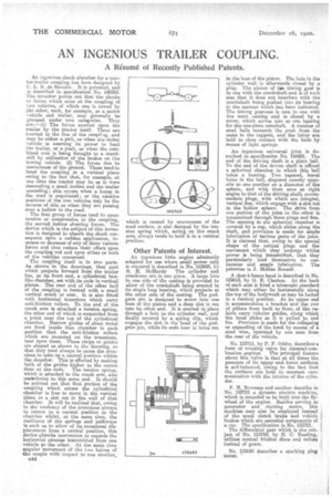
An ingenious shock absorber for a tractor-trailer coupling has been designed by C. L. B. de Saunier. It is patented, and is described in specification No. 140369. The inventor points out that the shocks or forces which arise at the coupling of two vehicles, of which one is towed by the other, such, for example, as a motor vehicle and trailer, may generally be grouped under two categories. They are :—(1) The forces exerted upon, the trailer by the tractor itself. These are exerted in the line of the coupliag, and may be either a pull, as when tee !MAW vehicle is exerting its power to haul the trailer, or a push, as when the combined unit is being brought to a standstill by utilization of the brakes on the towing vehicle. (2) The forces due to unevennesi of the ground. These tend to bend the coupling in a vertical plane owing to the fact that, for example, at one time the tractor may be as it were descending a small incline and the trailer ascending; this occurs when a hump in the road is negotiated; or the relative positions of the two vehicles may be the reverse of this as when they are passing over a hollow in the road.
The first group of forces tend to cause tension or compression in the coupling, the second induce sheering forces. The device which is the subject of this invention is designed to absorb the shock consequent upon a sudden application, increase or decrease of any of these various farces and thus reduce their effect upon the coupling rod and upon either or both of the vehicles concerned.
The coupling itself is in two parts. As shown, in the drawing; that part which projects forward from the trailer has, at its front end, a cylindrical boxlike chamber, set with its ends in vertical planes. The rear end of the other half of the coupling is formed with a small vertical crank or arm. It is also fitted. with horizontal trunnions which carry anti-friction rollers. To the end of the crank arm is attached, a tension spring, the other end of which is suspended from a. point near the top of the cylindrical chamber. Narrow guides of sheet metal are fixed inside that chamber in such position that the anti-friction rollers which are mounted on the trunnions, bear upon them. These strips or guides are shaped as shown in the drawing, so that they tend always to cause the teentams to take up a central position within the chamber. This is effected by making both of the guides higher in the centre than at the ends. The tension spring, which is attached to the crank arm, also otierbributes to this same end. It should be pointed out that that portion of the coupling which enters the cylindrical chamber is free to move in the vertical plane in a slot cut in the wall of that chamber. It will be realized that, owing to the tendency of the trunnions always to return to a central position in the chamber whilst, at the same time, the resilience of the springs and pathways is ouch as to allow of its occasional displacement from a central position, this device absorbe unevenness as regards the horizontal stresses transmitted from one vehicle to the other. At the stuns time singular movement of the two halves of the couple with respect to one another, 044 which is caused by unevenness of the road surface, is also damped by the ten. sion spring which, acting on the crank arm, always tends to hold it in a vertical position.
Other Patents of Interest.
An ingenious little engine admirably adapted for use where .mall power only is required is described in No. 153685, by R. H. McIiardy The cylinder and crankcase are in one piece. A large hole In one side of the casting is provided to allow of the crankshaft being erected in it single long bearing, which projects at the other side of the casting. The gudgeon pin ie, designed to screw into one be of the piston and a deep slot is (nit into its other end. It is erected in place through a hole in the cylinder wall, and finally secured by a spring clip, which engages the slot. in the head of the gudgeon pin, while its ends bear in holes cut
in the boss of the piston. The hole in the cylinder wall is afterwardsclosed by a plug. The pinion of the timing gear is in, one with the crankshaft and is of such eize that it does not interfere with the crankshaft being pushed into ita bearing in the manner which hae been indicated. The timing gearcase is east in one with the main casting and is dosed by. a ,cover, which serves also as one bearing for the one-piece camshaft. A number of steel balls transmit the push from the cams to the tappets, and the latter are held in close contact with the balls by means of light springs.
An ingenious universal joint is described in specification No. 150981. The end of the driving shaft is a plain ball. To the end of the driven shaft is affixed a spherical chamber in which this ball takes a bearing. Two tapered, bored holes in the ball, disposed exactly opposite to one another on a diameter of the sphere and with their axes at right angles:to that of the driving shaft, aceemmodate plugs, with which arc integral, vertical fins, which engage with a slot out in the hollow sphere. The drive from one portion of the joint to the other is transmitted through these plugs and fins. The opening to the spherical chamber is covered by a cap, which slides along the shaft, and provision is made for ample lubrication of various parts of the joint. It is claimed that, owing to the special shape of the conical plugs and the movement which they undergo whilst power is being transmitted, that they particularly lend themselves to continuous and ample lubrication. The patentee is J. McGee Russell.
A ohar-a-bene_s hood is described in No. 153613, by G. E. Claxton. At the back of each seat is fixed a telescopic standard which may either lie horizontally along the top of the bodywork or may be locked in a vertical position. At its upper end it accommodates a bracket -and the row of pillars from haok to front of the vehicle carry tubular guides, along which the hood slides as it is pulled to and fro. Provision is made for the collapsing or expanding of the hood by means of a steel wire, operated by one man from the raw of the vehicle.
No. 153711, by P. F. Oddie, describes a farm of rotating valve for internal-combustion engines. The principal feature about this valve is that at all times the pressure of its upper and lower surfaces is soli-balanced, owing to the fact that the surfaces are both in constant come manieation with the interior of the cylinder.
F. H. Bowman and another describe in No. 153721 a dynamo electric machine, which is intended to be built into the flywheel of the engine. Besides serving as generator and starting motor, this machine may also be employed instead of the usual clutch brake and vehicle brakes which are essential components of a car. The specification is No. 153721. The differential gear which is the subject of No. 153759, by H. C. Reading, 'utilizes conical friction discs and rollers instead of gears.
No. 153680 describes a sparking plug tester.