


For DRIVERS, MECHANICS & FOREMEN.
Page 29
If you've noticed an error in this article please click here to report it so we can fix it.
TEN SHILLINGS is paid to the sender 6,f any letter which we niablish on this page, and an. EMIA FIVE SHILLINGS to the sender of the one which we select as being the best each week. All notes are edited before being published. Mention your employer's name, in confidence, as evidence of good faith. Address, D., M. and E., "The Commercial Motor," 7-13, liosebery Avenue, London,. E.G. 2,
Lamps Alight.
On Saturday, January 1st, light your lamps at 4.29 in London, 4.17 in Edinburgh, 4.16 in Newcastle, 4.29 in Liverpool, 4.30 in Birminghaan, 4.39 in Bristol, and 5.14 in Dublin.
Tips for Locomobile Lorries.
The sender of the following communication has been awarded the extra, payment of 5s, this week.
[2,171] " J.L." (Tenbury Wells) writes :—" There are sure to be many Locomobile and Riker lorries on our roads just now which have been bought, either directly or indirectly, from. the Disposals Board. The following tips. concern that make of chassis (for they are one and the same, though of different dates of manufacture) and may aid many drivers in getting the best from their vehicles.
"With many of the older ones we had trouble owing to breakage of the induction pipe flanges. On later models the makers fitted pipes having thicker flanges and eliminated that trouble. If, however, the lorry which any reader is driving has flanges on the induction pipe which are no more than in. thick, he may expect trouble, and a simple way to prevent it
is to fit s plain bent stay of 1 in. by in. bar, fastening one end to the stud on the aluminium air muff, and the other to the top right-hand set-screw on the pump skew-gear cover. This will support the pipe and relieve the flange accordingly. Should a crack have developed already, the pipe may easily be supported temporarily, pending the provision of a new manifold with thicker flanges, by fitting a hook stay. This is made in two parts. A piece of round bar screwed at one end and hooked at the other so as to pass round the manifold is passed through a. piece of flat bar resting on the other side of the cylinder casting. It is then nutted up and tightened against the bar.
" Aluminium nuts were, at one time, used to adjust the air valve springs on the carburetter. There Will only be a few of these, I fancy, remaining. They should be replaced with lorass or steel nuts as soon as possible.
"For the engine as a whole I have nothing but praise. It pulls like a steam-engine. The crankcase is of special yellow metal, every stud is pinned, and therefore cannot get loose, and it is only possible to find about four threads in aluminium anywhere on the chassis. I do recommend, however, that the governor balls be removed. " A clutch stop is an advantage and can easily be made from a piece of old spring leaf of 2 in. by in. section. It should be bolted on to the clutch fork and positioned so that it presents a flat face to the hack of the clutch member • that face should be lined with a piece of Ferodo. This remark about a clutch stop applies only to the Locomobile chassis and not to the Riker, which has a. different type of fitting.
'Now and again we had trouble with broken radius rods, but ultimately found this to be due to tightening up the rear end too much. These rods should always be freely movable on the rear axle. The torque rods, too, gave us similar trouble, cracking up from the bottom near the rear end, just in front of the lug which takes the pivot pin. This we traced to the saddles carrying the rear springs. They are fitted with brass bushes, and these, in a good many cases, were found to have seized. It is not at all difficult to discover whether these bushes _are
in good order or not, but to put them right if they are wrong is far from easy. Begin by disconnecting the front end of the torque rod; then essay to move it up and down, having first taken the weight of the chassis and of the rear springs. If it can be moved, then it is safe to conclude that the bush is all right. If it cannot, then there is trouble in store. Jack up the rear axle and chassis independently. Take off the rear wheel on the side which is out of order, remove the spring clips and allow the spring to come
up clear of, the saddle. The saddle can then be driven off and the bush eased. It should be well .oiled before being replaced and a plentiful supply of lubricant should always be sprovided. In difficult cases it is sometimes necessary to warm the saddle with a blow lamp before attempting to drive it off the axle.
. "Naturally, the performa,nee of a lorry depends very considerably upon its driver; but I do know of one chassis, regularly employed on heavy duty in France for four years, which, at the end of that time, still had the original split pins in the joint bolts of the crankcase.",
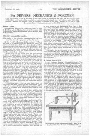
A Cheap Bench Drill.
[2,172] "Constant Reader" (Wisbeeh) writes.:—"The accompanying sketch (which we have had redrawn.— En.) shows how an ordinary joiner's brace may easily and cheaply be converted into a powerful bench drill. I have erected apparatus of this kind in my own work. shop, and, with its aid, I find it quite easy to drill holes varying in diameter from an eighth of an inch up to half an inch, in all kinds of metals.
"Near one end of the bench, erect a. wooden post about 1s ins, high and 3 ins, square section. This is indicated at B. Hinged to the top of it, using a stout gate hinge, is a., piece of 5 in, by 1 in. plank 4 ft. long, shown as C. Near to the other end of the plank erect a couple of guide posts (D), using for this .pnrpose 11 in. square section timber. They must also be rigidly secured t6 the bench, and may be tied together by a cross piece (E), which also:serves to take the weight of the plank when it is not in use. A couple of nails, shown at F, are hammered through the plank at the top side so that they project below sufficiently to engage the upper handle of the brace."