


Patents Completed.
Page 16
If you've noticed an error in this article please click here to report it so we can fix it.
WATER-FEED SUPPLY.— Ogden. — No. 5,142, dated March nth, r905.—The pump supplies water by the conduit (c) and passage (d) to the boiler_ The conduit (c) is controlled by a lift valve (b), normally kept upon its seating by a spring (y). At the top of the valve is a piston (a), which fits loosely in a chamber Ig) connected by a pipe (h) with the boiler (j). When the water level is below the piston (a), the valve (b) opens radially and permits water to pass to the boiler, but as it rises above the piston and the pipe (It) the chamber Lg) becomes filled with water, so that the valve (5) opens sluggishly, as the water above the piston has to be discharged through the pipe (h) or pass the loosely-fitting piston (a). The pipe (h) may be controlled by a valve (k), so that the amount of opening permitted at this point can be adjusted. When no .water is above the piston (a) the valve opens quickly and water is freely admitted to the boiler.
VALVE REMOVER.— Aliffiandery. — No. 16,021, dated August 4th, 1905.--A clamping frame (a) having a rod ■?) free to slide in a sleeve (c) secured to the top of the frame is placed over the valve, so that the lower end of the frame engages the washer (o), against which the spring (pi bears. The cover of the valve chamber being removed, a rod (1) is lowered so that it rests upon the valve (a). A screw (f) carried by a swinging frame (e) is then swung into position above the rod 11), and by strewing this down the spring (p) is compressed so that the locking-pin (q) can be removed. A frame j), free to slide upon the sleeve (c) and having pivoted to its base a ring (k), is then 'nought into position upon the top of the valve chamber and secured to the sleeve (c) by a setscrew (i). By this means the tension upon the spring (it) is maintained whilst the screw (f) is swung out of the vertical position to permit the rod (1) to be raised and the valve (a) lifted out.
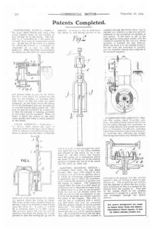
ELECTRIC IGNITION DEVICE.— 1-43 Pontois, New York.—No. 858, dated January 16th, 19o5.—The object of this invention is to provide an ignition device in which an alternating magneto-current is employed, and to allow for simultaneously varying the moment of ignition and the supply of current. The permanent magnet takes the form of a steel band (6) wound to form a laminated annular body, in which poles (7, 9, and to) are mounted. Coils (it and x2) are wound round the poles (9 and io) and an armature is carried by the fly-wheel and rotates opposite the poles of the magnet. The coils (it and 12) are so connected with a switch (24) that either coil may be connected with the ignition device, or two in parallel therewith. The switch or lever (24) has pivoted to it an arm (221, interposed between the cam (57) and the ignition tappet (20. By moving the lever to the left ignition takes place later, and the current is
supplied through the switch shoes (34) by the coil (ii), which is in the best position relatively to the crankshaft for ignition at this period. If the lever is put to the right, ignition takes place earlier, and the current is supplied by the coil (12), whose situation is suitable for this purpose. When the lever is in the middle position, the two coils are connected in parallel, and the requisite current thus supplied at the moment required.
A CARBURETTER ADJUNCT.—Merritt.—No. 25,603, dated November 24th, 19o4.—In multi-cylinder engines the incoming air passes through the carburetter at such a high velocity that proper vapourisation is commonly not effected, especially where heavier hydrocarbons are employed. To overcome this difficulty the charge, after being atomised in any suitable device, is brought in its passage into the cylinder against a disc (d) having a series of projections fe). The projections are hollow, and the chamber in which the disc is situated is jacketed so that it is heated by the exhaust from the conduit (c). That part of the charge which is not properly vapourised is caught by a gauze disc (Li, and discharged through the hollow stem (i).