


Complex Gear for Easy Booster-engine Control
Page 36
If you've noticed an error in this article please click here to report it so we can fix it.
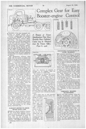
A Resume of Patent Specifications That Have Recently Been Published. Copies may be Obtained from the Patent Office, Price 11each
CHASSIS of the type equipped with what is usually known as a " booster " engine form the subject of patent No. 546,237, by the Gear Grip.ding Machine Co., Detroit, Michigan, U.S.A. The object is to provide a vehicle that can suit its engine power to the load, and the whole subject is based on a matter of economics. Three main factors are concerned, namely, first cost, the saving effected by running an engine for the greater part of its life .under conditions approaching those for maximum efficiency, and the maintaining under all road conditions of speeds that are roughly constant for all vehicles.
This specification, however, deals chiefly with the system of control, and relates to the use of one or more booster engines in addition to the main power unit. A six-wheeled tractive unit is instaneed, with two engines. The main engine (A) and transmission are connected to the leading pair of rear wheels, the general layout being conventional. The second engine (B) is mounted above the frame behind the driver's cab, and is coupled to the third axle by a separate transmission system. The radiator of this engine, actually in two sections, is cooled by air collected alongside the cab and directed to the centre by 'scoops. Both cooling systems are interconnected, so as to ensure an easy start, and efficient performance from the outset, when the second power unit is required. COntrol arrangements permit normal operation of either engine alone, whilst during dual working they ensure that the same gear ratios are engaged together, and that both clutches operate simultaneously. A somewhat complex system is entailed in which electric switches, . vacuum-operated contacts ' and Mechanical apparatus all play their part. 'Much ingenuity has been exercised, and everything made as simple as 'possible for the driver, but we surmise that the average British maintenance engineer would look rather aghast at the elaborateness of the wiring, piping; mechanism, etc..
DASH-POT DEVICE TO CHECK BRAKE BACK LASH CROM the Bendix Aviation Corpora tion South Bend, Indiana, U.S.A., comes in patent No. 546,234 a design for a brake mechanism in which the shoes abut on one anchorage or another, according to the direction of rotation, The subject of the patent is a cushioning device to prevent shock when the direction of rotation is changed, as, for example, when the vehicle makes an uphill stop.
We illustrate in section one of the two hydraulic cylinders. It contains two pistons, one of which acts as an expander, whilst the other forms the abutment, the choice of piston for these respective functions being governed by • the direction of rotation, The cushioning device consists of a spacer plug (1) firmly attached to the wall Of the cylinder, and housing, as a matter of convenience, the cup-washer springs. This plug is provided with small grooves along its length, and so acts as a dash-pot when reversal of rotation Occurs.
Each brake shoe is also provided with a constant-clearance device consisting of a hard non wearing block which runs on the brake dam and sets t h e . adjustable " off " position. This simple device is said to he so satisfactory as to eliminate the need for manual adjus tment throughout the whole life of the facings. DISTORTING CLUTCH PLATE TO AVOID GRABBING
T(ipromote smoothness of operation s the object of a design of clutch plate shown in patent No. 545,889 by General Motors Corporation, Detroit, Michigan, . U.S.A. . The -object is achieved by causing the engaging pressure to effect a distortion of the steeldriven plate.
Two methods are described: One, shown at A, utilises flat facings and a dished plate which is flattened under pressure, as at B; the other, shown at C, employs a normally flat steel plate gripped between friction faces having two steps, blended by a slope and, when fully engaged, the plate. is depressed to correspond with the shape of the facings, as at D. The net effect is the same in both cases.
It will be noted, by reference to the drawing mAked E. that the steel plate is slotted so as to form separate segments, A .feature of the patent is that the sloping portions of the friction material are tangential, so that each face consists, virtually, of three superimposed triangles.
COMPOSITE BEARING OIL-RETAINER
BALL and roller bearings, being precision mechanisms, are liable, to damage from the entry of minute foreign bodies. To exclude dirt, and at the same time to retain the lubricant, is the object of a sealing device shown in patent No. 545,934 by the Hoffmann Manufacturing Co., Ltd., Chelmsford. In the example illustrated—a singlerow ball hearing—the sealing device consists of a ,thin metal washer (1) bonded to a shaped washer (3) made of rubber. The composite ring thus formed is split like a piston ring and can be sprung into position in a groove formed in the outer race. The bead (4) and the curve (2) are both produced by the compression of the rubber, and form effective seals on both races.