


A Time-controlled Decompressor
Page 36
If you've noticed an error in this article please click here to report it so we can fix it.
A Resume of Patent Specifications That Have Recently Been Published. Copies may be Obtained from the Patent Office, Price 11each
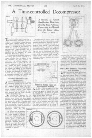
TO enable hand or electric starting to be more easily. performed on an oil engine, a compression release 'is sometimes 'fitted, usually taking the form of a trip -mechanism -on the exhaust valves. A scheme of this nature, in which the period of decompression is automatically -time;controlled by : a dashpot,. is shown in patent No. 559,575,... by A. Sanders,1, Park Crescent, Roundhay, Leeds.
• To illustrate.the principle, the drawing shows the .scheme applied to. a single cylinder, but, of course, it can he extended to any number of
cylinders. A . sliding cam-rod (1)
co-operates with collar (5) or the
exhaust tappet, so that it can permit the tappet to work normally shown) or, if pushed to tha,right, lift the tappet by means of ;.the sloping face (.4). When in the latter position, a spring 3), -attempts to return it to. norrrrai, but the -action is delayed by a pneumaticdashpot (2), .which :can ' be adjusted, for speed of return.
COOLING PISTONS By OIL : , -CIRCULATION , A. PISTON-COOLING-idea, 'in which .circulated engine' oil.is used -,to carry away the heat is shown: in-patentNo. 558.819, which bears, the wellknown name, H. Rieardo,'21, Street, London, S.W.1, The. piston used is formed in two parts,, a ring. skirt portion and an miter mernbe,i carrying the gudgeon pin
'rale pin-carrYlrig portion
bolted on to the crOwn, ?.;ine of' the mating faces being cut into ,zavelial serrations to 'leave groOves resembi&ng the spokes of a wheel. The.„skirt and the, inner member are shaped to form both an, annular chambe'r -(3) and a larger chamber '(4); these are' connected
by narrow clearances, which —
eventually Open • tothe
crankcase.
-,'The cooling 'Oil is pumped up the drilled connecting rod and flows around a groove outside the gudgeon-pin. bush*.. From here it traverses the central space 2 and flows thiiviardi through the seirationsi reaching space 3. • The oil, now. hot, flows into chamber 4, whence it isnally cliseharged, returning the crankcase by gravity.
• In order that the inertia forces in the oil; created by. the reciprocation, can be usefully employed in assisting the flow,
• it is proposed to supply the oil, in a series )of timed spurts.' This i$ achieved by incorporating a port in the -big-end bearing which is open for only a certain -period in each reVolution. In the &awing, the port is shown as a hole .(5) in the crankpin which discharges thrmigh holes 6 in the bearing shell daring a 'certain angle. These -holes, of course. lead to a channel feeding the drilled Connecting rod.
.KEEPING TYRES FREE OF PUNCTURING AGENTS , • •
A PUN CTUREPREVENTING • . PI device, which either remoVes the , puncturing agent or warns the driver
of its presence, is shown in patent No. 559,577, by J Crosb-61, F.Ilwood
• Road, Wood Bank, Stockport. -The drawing 'Shows a Side elevation • of the,.device which is said to be suit:• able for heavy, vehicles. Pivoted about' ,point 1, is ,a swinging arni. (2) which has mounted upon it a. blade (3), The blade is arranged to be a close fit upOn 'the tyre tread, and i ..capable Of
knocking out an small flints . or nails on their first journey around the wheel;
Should a. seriouS Iprojection he encountered, the arm (2) cwould be lifted 'on eVery revcilution of the wheel, and 'this is arranged to work an eleetri: contact which would give. warning to
the driver: • • •
EQUALIEED BpAkIt■io---F.oltivrAftb AND REVERSE WEN a vehicle is le
' being decerated, .an additiimaiWeight iS transferred ..to the ,frout .wheels, And it is ;:t.istm.I,
• therefore„ to arrange for more Tow.erfpl braking at the front In re:Vet-Se; the .'extra load is applied to the rear wheels-, and the design Should: alltA' for thisz...
'A sheine Iii6renSed'bralting . applied to.; WhicheYer-pair of :
leading, forms .the subject of-,pateut No.
559,305, from-Eendix. Aviation Corporation, ..South Rend, Indiana, U.S.A. . Each brake iS fitted Nvith' a.,pair of hydraulic expariderS, containing a Sinall piston (1) and -L larger one -(2). These pistons are Stepped. to forin-'an abut. merit against the cylieders; ineetiug one ' end or the 'other, according to the direc, {ion of rotation tiVtlie brakedrUm. • Assuming anti;cloCkwise rotatibii, th front.ihrakes. (F)...wauld'he operated by • the .largee, pis tons (2), because .thejead imposed ,by the ,iloating shoes would firmly prevent the Sina,...11er Pr tont froin MOvin; On the rear brake'S • (R). reversstkt .• and so: in this cage; the flOat. in action loads the large cylinders; leaving the smaller ones to operate the b'rakes at • less pressure, If the vehicle lie travelling "hackWards, the whole action I's automatically t'everSecl 'and. the' rear 'WheelS are then braked harder than
• the front. •Siich special provision for reverse braking,. must • be cons41preci in the,nature of a refinernent.