


A New Anti-rolling Device
Page 72
If you've noticed an error in this article please click here to report it so we can fix it.
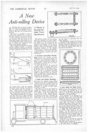
AS11111' LE and, vie should imagine, very efficient anti-rolling device is shown in patent No. 345,526 by Pierre Wilmart, 42a, Rue de In Longne-Haie, Brussels.
The device is intended to stop or diminish the tendency for a vehicle to roll when passing over uneven • ground or when cornering, and does not in any way interfere with the action of the supporting springs, which might be even more flexible than usual, as all stresses due to rolling are transferred from them to the auxiliary springs.
The arrangement consists of a strong tubular member, capable of resisting torsion, mounted in bearings which may be either supported by the frame or by ilia springs close to the rear shackle. The ends of this member are flattened so that springs can be attached to them. These springs extend forward and are attached to the main springs near to where they join the rear axle.
The auxiliary springs are so arranged that they will act in either direction, the leaves being held together by clips. file action of the device is as follows :— The tubular member and the springs which are attached to it form a structure which will resist torsion to an extent which may be governed by the strength of its springs. Leaves can be added to these springs to any extent without reducing the flexibility of the supporting springs, as the tubular member is free to rotate in its bearings.
Any tendency to roll must cause the auxiliary springs to depart from their normal form.
A Vacuum-controlled Clutch.
T.= patent, No. 313,452, of Otto
Erdelen, 51 Goltzstrasse, Berlin, relates to a vacuum-controlled clutch, in which a piston working in a cylinder is connected by a slotted rod to an extension of the clutch lever.
A pipe (E) leads to the source of vacuum, whilst a rotating valve communicates either to atmosphere at R or to the ball valve of the vacuum pipe. The rod (0) is described as being coupled to the accelerator, so that the clutch is withdrawn when the accelerator is released, and is engaged when the accelerator is depressed.
This patent has become void.
A Ball and Roller Bearing.
IN patent No. 345,181 George Salter and Co., Ltd., and B. Trubshaw, both of West Bromwich, describe a form of roller bearing in which the rollers are supported, in relation to their cages, by means of balls.
The rollers are of the kind which are formed by helically wound strips of spring steel. In the end of each roller is a hollow nearly approaching the depth of half a ball. Similar hollows are formed in the cage, and balls are placed between the cage and the ends of the roller. Distance bars are riveted into the cages to hold. them and the rollers together.
The specification claims that friction is reduced by the insertion of a ball between the moving parts, but we cannot follow this, as rubbing and not rolling contact is present when halls are mounted in this fashion..
A New Body for Dust Carts.
THE body for dust collecting described
in patent No. 345,059, by J. B. Glover, C. B. Hitchins, and Tuke and Bell, Ltd., Carlton Engineering Works, Lichfield, is of simple design.
It is intended to be mounted on a low-built chassis, and is provided with removable steps at the rear, so that the loaders can step up into the body.
A movable partition (11) is provided, which when the vehicle is unloaded occupies the position shown, but can be moved to three positions farther to the rear as the loading proceeds, bolts and bolt holes being provided for securing it.
A pedal (15) when pressed opens a lid, which closes again by its own weight. As the partition is moved rearwards the lid moves with it, and the space previously occupied by the lid is covered by a fabric sheet, which is stored in the space between the body and the driver's cab.
This cover is provided at intervals with slats, which rest on the edges of the body and so support it.
The emptying of the body is effected in the usual manner, by tipping