


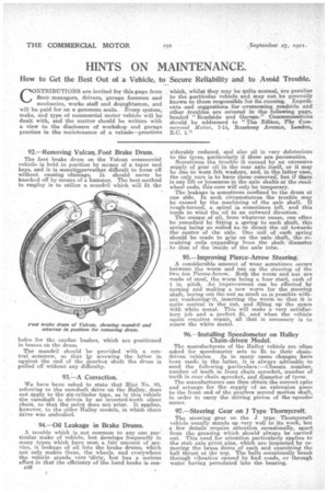
92. — Removing Yulcan,„Foot Brake Drum.
Page 32
Page 33
If you've noticed an error in this article please click here to report it so we can fix it.
The foot brake drum on the Vulcan commercial vehicleis held in position by means of a taper and keys, and it is sometimeemrather difficult to farce off without causing ridamage. It should never be knocked ryff by means of a hammer. The hest method to employ is to utilize a mandril which will fit the holes foe the eardan bushes, which are positioned in boesee on the drum_
The mandril should 'be provided with a central setscrew, so that ley screwing the latter in against the end of the gearbox shaft the drum is pulled off without any difficulty.
93.:—A Correction.
We have been asked to state that Hint No. 83, referring to the camshaft drive on the Halley, does not apply to the six-cylinder type, as in this vehicle the camshaft is driven by an inverted-tooth silent chain, so that the point does not arise. It applies, however, to the older Halley models, in which chain drive was embodied.
94.—Oil Leakage in Brake Prams.
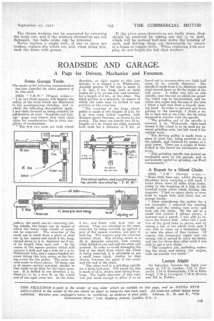
A trouble which is not common to any one particular make of vehicle, but develops frequently in many types which have seen a fair amount of service, is leakage of oil into the brake drums, which not only makes these, the wheels, and everywhere the vehicle stands very "dirty, but has a serious effect in that the efficiency of the hand brake is con c42 siderably reduced, and also oil it very deleterious to the tyres, particularly if these are pneumatics.
Sometimes the trouble i caused by an excessive supply of gear oil in, the rear axle itself, or it may be due to worn felt washers, and, in the latter case, the only cure is to have these 'removed, but if there ia any lift or looseness in the axle shafts at the roadwheel ends, this care will only be temporary. The leakage is sometimes confined to the drum at one side. In such circumstances the trouble may be caused by the machining of the axle shaft. If rough-turned, a spiral is sometimes left, and this tends to wind the oil in an outward direction. The escape of oil, from whatever cause, can often be remedied by fitting a spring to each shaft, this spring, being so eoiled as to direct the oil towards the centre of the axle. One coil of each spring should be made to grip on the axle shaft, the remaining coils expanding from the shaft diameter to that of the inside of the axle tube.
95.—Improving Pierce-Arrow Steering. A considerable amount of wear sometimes occurs between the worm and nut ea the steering of the two ton Pierce-Arrow. Both the worm and nut are made of steel, the worm being a four start, each of 1 in. pitch. An improvement can be effected. by turning and making a Pew worm for the steering shaft, boring out the nut as much as is possible without weakening" it, inserting the worm, so that it is quite central in the nut, and -filling up the space with white metal. This will make a very satisfactory job and a perfect fit, and when the vehicle again requires repair, all that is necessary is to renew the white metal.
96.--Installing Speedometer on Halley Chain-driven Model.
The manufacturers of the Halley vehicle are often asked for speedometer sets to fit to their chaindriven vehicles. AS in many cases changes have been made in the'latter,, it is .always advisable to send. the following particulars: —Chassis number, number -of teeth in front chain sprocket, number of teeth in. aver chain sprocket, Lnd diameter of tyres. The manufacturers can then obtain the correct ratio and arrange for the supply of an extension piece to the front end of the gearbox second motion. shaft, in order to carry the driving pinion of the meter.
97.—Steering Gear on J Type Thornycroft.
The steering gear on the J type Tharnyeroft vehicle usually, stands up very well to its work, but a few details require. attention occasionally, apart, from the greasing which should always be carried out. This need for attention particularly applies to the stub axle pivot pins, which are inspected by removing the brass dome of each and examining the ball thrust at the top. The balls occasionally 'break through vibration caused by bad roads, or through water having percolated into the hearing.
The thrust washers can be separated by removing the large nut, and if the washers themselves are not damaged, the balls alone can be renewed. Never replace a single ball; if one or more are broken, replace the whole set, and, when doing this. Pack the dome with grease. If the pivot pins.,thernselves are badly worn, they should be removed by taking out the: in. bolt, which will be noticed half-way down the housing of each, and driving them out downwards by means oi a brass or copper drift.. When replacing with new pins, do not forget the felt dust washers