


THE PULHAM COMPRESSED GAS SYSTEM.
Page 10
If you've noticed an error in this article please click here to report it so we can fix it.
FOR SOME WEEKS past THE COMMERCIAL MOTOR has been following some interesting experiments which have been in progress by Messrs. Pulham and Co., Marine • Garage, Bexhill-onSea. We were fully aware that the compression system was being favoured, and that the installation would possess certain novel features. The system has been tested •under practical conditions with promising results.
The reservoir proper comprises a nest of three cylinders, which in the installation in question are mounted on the running board. The cylinders, made from seamless steel tubing used in artesian well sinking, 6 ins. internal 'diameter, with wall in. thick, are about
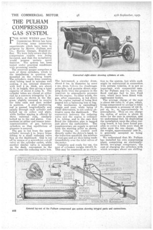
ft. in length, thus giving a total capacity of about 2 cubic ft. The cylinder tubes are dosed at either end by a common triangular i4 in. steel plate,as shown in the diagram, slightly recessed to receive the. tube ends and then welded in position. • A steel reinforcing rod is passed longitudinally and axially through each cylinder and boltedup on either end plate, while further staying is offered by three external. rods, similarly bolted up to the end plates. Connections at, either end ensure intercommunication of .gas between cylinders so that equilibrium of pressure is assured.
The gas is .led from the upper cylinder through -A in. heavy brass tubing to . a small reducing valve box on the dashboard. Gas is cut on' by means of a screwdown cut-off valve at the cylinder ontlet, while another similar valve is mounted on the dash, convenient to the driver, near the reducing valve box. The last-named, a. cimular drum, about 6 ins, in diameter by some 4 ins, deep, follows thc diaphragm principle, and permits direct stepping down from the pressure in the reservoir to atmospheric pressure for the engine. In other-words, the gas, after expansion, is led direct to the engine instead of being first passed into a balancing box or bag.
The mechanism is exceedingly simple and neat, while being of small dimensions, is not unduly •ebtrusive upon the dashboard. The connection between the reducing -valve and the engine is ordinary
in, tubing, and in the cars thus fitted the induction pipe is tapped just above the carburetter. The supplementary air supply is carried from the steering pillar as shown, thus bringing its control cock directly under the driver's hand, to the induction manifold, the mixture of coal-as and air thus being made immediately over the inlet valves of the motor.
Complete and ready for use, the nest of cylinders weighs 650-675 lb. This may be construed as an objec
tion to the ustern, but while such might be maintained in connection with private vehicles, it is not so important with commercial cars. So far Pulhain and Co. have Confined coal-gas fuel to two Ford cars, which have been fitted with eight-seater bodies.
The average charge of the nest is about 300 cubic ft. of rgas, which, being compressed to occupy 2 cubic ft.,. represents a pressure of 150 lb. per sq. in., or approximately 10 atmospheres. •Thuson one charge the radius of action is about 25 miles for the cars in question, and we understand that, by diiPlicating the installation upon the ether running board, it has been found possible.to cover a little more than 50 miles upon the one charge. • But the weight, approximately 1400 lb., is generally accepted as being excessive.
We understand that Mr. Pulhain has installed his own compressing plant, comprising an electricallydriven twolitage compressor, the cost of charging the cylinders with which averages about ope