


Valves as Engine Brakes • T HE braking effect of an engine
Page 62
If you've noticed an error in this article please click here to report it so we can fix it.
when driven by the vehicle is often thought to be caused by compression, but this is largely wrong, because most energy absorbed on, the compression stroke is immediately returned on the succeeding ,.expansion stroke. Such retarding effect as may be apparent results entirely, from friction and possibly compression leakage.
To obtain real braking from this method, the air must be compressed and then allowed to escape at top dead centre, so that no energy is stored in the cylinder. Such a scheme forms the subject of patent No. 697,841 (P. and B. Lowe, 209 Fleetwood Road, Thornton-Cleveleys, Blackpool). It is said to be particularly suitable for large oilengined vehicles.
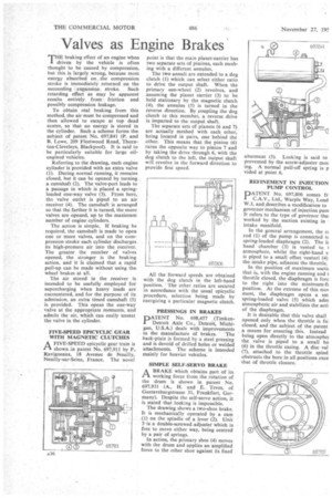
Referring to the drawing, each engine cylinder is provided with an extra valve (1). During normal running, it remains closed, but it can be opened by turning a camshaft (2). The valve-port leads to a passage in which is placed a springloaded one-way valve (3). From here, the valve outlet is piped to an air receiver (4). The camshaft is arranged so that the farther it is turned, the more valves are .opened, up to the maximum number of engine cylinders.
The action is simple. If braking be required, the camshaft is made to open one or more Valves, and on the compression stroke each cylinder discharges its high-pressure .air into the receiver. The greater the number of valves opened, the stronger is the braking action, and' it' is claimed that a rapid pull-up can be made without using the wheel brakes at all.
The air stored in the receiver is intended to be usefully employed for supercharging when heavy loads are encountered, and for the purpose of its admission, an extra timed camshaft (5) is provided. This opens the one-way valve at the appropriate moments, and admits the air, which can easily unseat the valve in the cylinder.
FIVE-SPEED EPICYCLIG GEAR WITH MAGNETIC CLUTCHES
AFIVE-SPEED epicyclic gear train is shown _in patent No. 697,911 by P. Ravigneaux, 18 Avenue de Neuilly, Neuilly-sur-Seine, France. The novel
point is that the main planet-carrier has two separate sets of pinions, each meshing with a different annulus.
The two annuli are extended to a dog clutch (1) which can select either ratio to drive the output shaft. When the primary sun-wheel (2) revolves, and assuming the planet carrier (3) to be held stationary by the magnetic clutch (4), the annulus (5) is turned in the reverse direction. By coupling the dog clutch to this member, a reverse drive is imparted to the output shaft.
The separate sets of planets (6 and 7) are actually meshed with each other, being located in pairs, one behind the other. This means that the pinion (6) turns the opposite way to pinion 7 and by taking the drive through 6, with the dog clutch to the left, the output shaft will revolve in the forward direction to provide first speed.
All the forward speeds are obtained with the dog clutch in the left-hand position. The other ratios are secured in accordance with the usual epicyclic procedure, selection being made by energizing a particular magnetic clutch.
PRESSINGS IN BRAKES'
PPATENT No. 698,457 (TimkenDetroit Axle Co., Detroit, Michigan, U.S.A.) deals with improvements
in the manufacture of brakes. The back-plate is formed by a steel pressing and is devoid of drilled holes or welded attachments. The scheme is intended mainly for heavier vehicles.
SIMPLE SELF-SERVO BRAKE
ABRAKE which obtains part of its working force from the rotation of the drum is shown in patent No. 697,931 (A., H. and E. Teves, of Gustavsburgstrasse 31, Frankfurt, Germany). Despite the self-servo action, it is stated that looking is impossible.
The drawing shows a two-shoe brake. It is mechanically operated by a cam _(1) on the spindle of a lever (2). Unit 3 is"a double-screwed adjuster which is free to move either way, being centred by a pair of springs.
In action, the primary shoe (4) moves with the drum and applies an amplified force to the other shoe against its fixed abutment (5). Locking is said to prevented by the screw-adjuster mou ing. A normal pull-off spring is p vided at point 6.
REFINEMENT IN INJECTION PUMP CONTROL
PATENT No. 697,806 comes fr C.A.V., Ltd., Warple Way, Lond W.3, and describes a modification to governor mechanism of injection pum It refers to the type of governor thai worked by the suction existing in • intake manifold.
In the general arrangement, the re rod (1) of the pump is connected tc spring-loaded diaphragm (2). The lc hand chamber (3) is vented to 1 atmosphere, whilst the right-hand s is piped to a small offset venturi (4) the intake pipe, adjacent the throttle.
In the position of maximum sued( that is, with the engine running and t throttle closed, the diaphragm is fore to the right into the minimum-ft position. At the extreme of this MON ment, the diaphragm opens a sm spring-loaded valve (5) which adm atmospheric air and stabilizes the acti, of the diaphragm.
It is desirable that this valve shall opened only when the throttle is fui closed, and the subject of the patent a means for ensuring this. Instead being open directly to the atmosphei the valve is piped to a small bo (6) in the throttle casing. A disc val (7), attached to the throttle spind obstructs the bore in all positions exce that of throttle closure. .