


A Dual-piston Two-stroke Engine
Page 54
If you've noticed an error in this article please click here to report it so we can fix it.
A Résumé of Patent Specifications that Have Recently Been Published
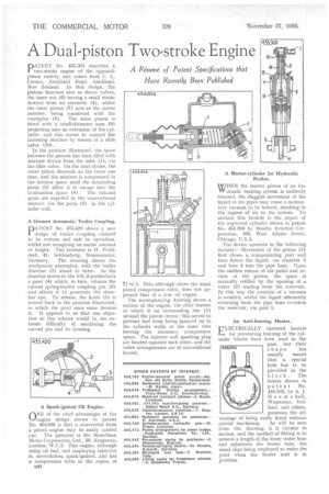
PATENT No. 455,301 describes a two-stroke engine of the opposedpiston variety, and conies from C. L. Cremer, Archibald Road, Auckland, New Zealand. In this design, the pistons function also as sleeve valves, the inner one (6) having a small stroke derived from an eccentric (4), whilst the outer piston (7) acts as the power member, being connected with the crankpins (5). The main piston is fitted with a small-diameter nose (9) projecting into an extension of the cylinder, and this 'serves to control the incoming mixture by means of a slide valve (10).
In the position illustrated, the space between the pistons has been filled with mixture drawn from the inlet (1), via the slide valve. On the next stroke, the outer piston descends as the inner one rises, and the mixture is compressed in the interior space until the descending ports (2) allow it to escape into the combustion space (8). The exhaust gases are expelled in the conventional manner, via the ports (3) in the cylinder wall.
A German Automatic Trailer Coupling.
PATENT No. 455,420 shows a new design of trailer, coupling claimed to he certain and safe in operation, whilst not occupying an undue amount of height. The inventor is H. Wohldorf, 41, Sehleusberg, Neumuenster, Germany. The drawing shows the mechanism uncoupled, with the trailer drawbar (3) about to enter.. As the drawbar moves to the left, it pushes hack a pawl (4) which, in turn, releases the curved spring-loaded coupling pin (2) and allows it to penetrate the drawbar eye. To release, the knob (1) is moved back to the position illustrated, in which the pawl once more detains it. It appears to us that one objection to this scheme would be the extreme difficulty of machining the curved pin and its housing.
A Spark-ignited Oil Engine.
()NE of the chief advantages of the L.lengine design shown in patent No. 454,924 is that a conversion from a petrol engine may be easily carried out. The patentee is the Hesselman Motor Corporation, Ltd., 66, Kingsway, London, W.C.2. This engine, although using oil fuel, and employing injection is, nevertheless, spark-ignited, and has a compression ratio in the region of B44 71 to I. This, although above the usual petrol compression ratio, does not approach that of a true oil engine.
The accompanying drawing shows a section of the engine, the chief feature oi which iS an outstanding rim (1) around the piston crown ; this serves to prevent fuel from being sprayed on,to the cylinder walls, at the same time leaving the necessary compression space. The injector and sparking plug are located opposite each other, and the valve arrangements are of conventional layout. WHEN the master piston of an byre draulic braking system is suddenly released, the sluggish movement of the liquid in the pipes may cause a momentary vacuum to be formed, resulting in the ingress of air to the system. To obviate this trouble is the object of the improved cylinder shown in patent Na. 454,854 by Bendix Aviation Corporation, 105, West Adams Street, Chicago, U.S.A.
The device operates in the following manner :—Movernent of the piston (5) first closes a compensating port and then -forces the liquid, via chamber 3 and bore 4 into the pipe lines. Uposi the sudden release of the pedal and return of the piston, the space is instantly refilled by the 'opening of a valve (2) leading from the reservoir. In this way the creation of a vacuum is avoided, whilst the liquid ultimately returning from the pipe lines re-enters the reservoir, via port 1.