 1
1 2
2 3
3 4
4 5
5 6
6 7
7 8
8 9
9 10
10 11
11 12
12 13
13 14
14 15
15 16
16 17
17 18
18 19
19 20
20 21
21 22
22 23
23 24
24 25
25 26
26 27
27 28
28 29
29 30
30 31
31 32
32 33
33 34
34 35
35 36
36 37
37 38
38 39
39 40
40 41
41 42
42 43
43 44
44 45
45 46
46 47
47 48
48 49
49 50
50 51
51 52
52 53
53 54
54 55
55 56
56 57
57 58
58 59
59 60
60 61
61 62
62 63
63 64
64 65
65 66
66 67
67 68
68 69
69 70
70 71
71 72
72 73
73 74
74 75
75 76
76 77
77 78
78 79
79 80
80 81
81 82
82 83
83 84
84 85
85 86
86 87
87 88
88 89
89 90
90 91
91 92
92 93
93 94
94 95
95 96
96 97
97 98
98 99
99 100
100 101
101 102
102 103
103 104
104 105
105 106
106 107
107 108
108 109
109 110
110 111
111 112
112 113
113 114
114 115
115 116
116 117
117 118
118 119
119 120
120 121
121 122
122 123
123 124
124 125
125 126
126 127
127 128
128 129
129 130
130 131
131 132
132 133
133 134
134 135
135 136
136 137
137 138
138 139
139 140
140 141
141 142
142 143
143 144
144 145
145 146
146 147
147 148
148 149
149 150
150 151
151 152
152 153
153 154
154 155
155 156
156 157
157 158
158 159
159 160
160 161
161 162
162 163
163 164
164 165
165 166
166 167
167 168
168 169
169 170
170 171
171 172
172 173
173 174
174 175
175 176
176 177
177 178
178 179
179 180
180 181
181 182
182 183
183 184
184 185
185 186
186 187
187 188
188 189
189 190
190 191
191 192
192 193
193 194
194 195
195 196
196 197
197 198
198 199
199 200
200 201
201 202
202 203
203 204
204 205
205 206
206 207
207 208
208 209
209 210
210 211
211 212
212 213
213 214
214 215
215 216
216 217
217 218
218 219
219 220
220 221
221 222
222 223
223 224
224 225
225 226
226 227
227 228
228 229
229 230
230 231
231 232
232 233
233 234
234 235
235 236
236 237
237 238
238 239
239 240
240 241
241 242
242 243
243 244
244 245
245 246
246 247
247 248
248 249
249 250
250 251
251 252
252 253
253 254
254 255
255 256
256 257
257 258
258 259
259 260
260 SCAMMELL HIMALAYAN PIP TRUCK
Page 130
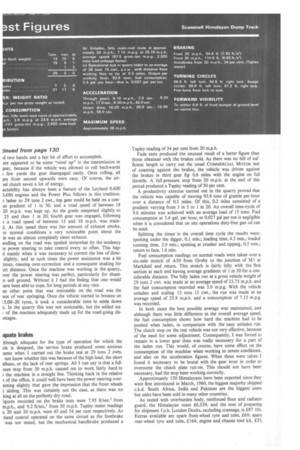
Page 131
Page 132
Page 135
If you've noticed an error in this article please click here to report it so we can fix it.
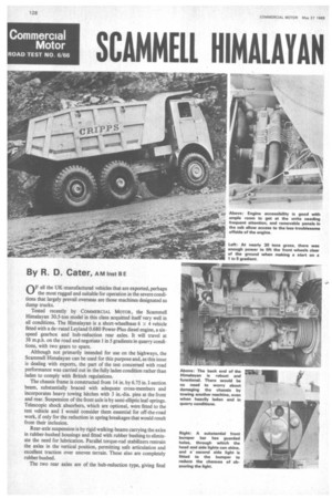
By R. D. Cater, A M Inst B E OF all the UK-manufactured vehicles that are exported, perhaps the most rugged and suitable for operation in the severe conditions that largely prevail overseas are those machines designated as dump trucks.
Tested recently by COMMERCIAL MOTOR, the Scammell Himalayan 30.5-ton model in this class acquitted itself very well in all conditions. The Himalayan is a short-wheelbase 6 x 4 vehicle fitted with a de-rated Leyland 0.680 Power-Plus diesel engine, a sixspeed gearbox and hub-reduction rear axles. It will travel at 38 m.p.h. on the road and negotiate 1 in 5 gradients in quarry conditions, with two gears to spare.
Although not primarily intended for use on the highways, the Scammell Himalayan can be used for this purpose and, as this issue is dealing with exports, the part of the test concerned with road performance was carried out in the fully laden condition rather than laden to comply with British regulations.
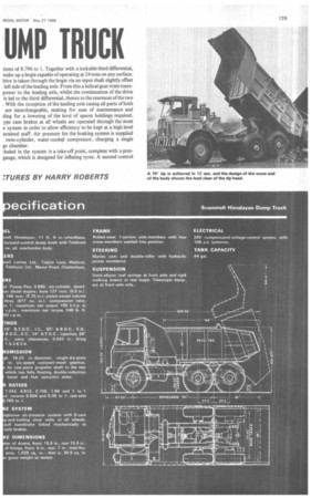
The chassis frame is constructed from 14 in. by 6.75 in. I-section beam, substantially braced with adequate cross-members and incorporates heavy towing hitches with 3 in.-dia. pins at the front and rear. Suspension of the front axle is by semi-elliptic leaf-springs. Telescopic shock absorbers, which are optional, were fitted to the test vehicle and I would consider them essential for off-the-road work, if only for the reduction in spring breakages that would result from their inclusion.
Rear-axle suspension is by rigid walking-beams carrying the axles in rubber-bushed housings and fitted with rubber bushing to eliminate the need for lubrication. Parallel torque-rod stabilizers restrain the axles in the vertical position, permitting safe articulation and excellent traction over uneven terrain. These also are completely rubber bushed.
The two rear axles are of the hub-reduction type, giving final tions of 8.796 to 1. Together with a lockable third differential, nake up a bogie capable of operating at 24 tons on any surface. lrive is taken through the bogie via an input shaft slightly offset left side of the leading axle. From this a helical gear-train transpower to the leading axle, whilst the continuation of the drive is led to the third differential, thence to the rearmost of the two . With the exception of the leading axle casing all parts of both are interchangeable, making for ease of maintenance and (ling for a lowering of the level of spares holdings required. ype cam brakes at all wheels are operated through the most e system in order to allow efficiency to be kept at a high level strained staff. Air pressure for the braking system is supplied twin-cylinder, water-cooled compressor, charging a single ge chamber.
Auded in the system is a take-off point, complete with a presgauge, which is designed for inflating tyres. A second control system is fitted in the air circuit to provide easy parking-brake operation during the many stops made for short periods when engaged on quarry works. This comprises a hand-reaction valve of the type normally fitted to tractive units for controlling trailer brakes.
In the case of the Himalayan, this valve controls brakes on all wheels, and I found it to be an extremely useful addition to the standard system. The main reason for this was that the ratchet parking-brake, which works on the four wheels of the rear bogie, become a bit tiring to apply and release continuously, particularly to release. When this was done, a powerful jar was transmitted up the left arm of the user. Once it was applied, however, the handbrake was extremely efficient and capable not only of holding the machine on a 1 in 5 gradient, but also of bringing it to a standstill.
Hydraulically powered steering is fitted as standard with the hydraulic power being supplied from an engine-mounted pump driven from the camshaft wheel.
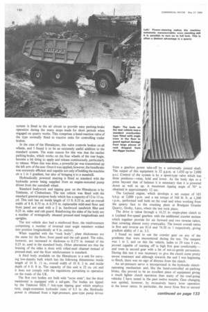
Standard bodywork and tipping gear on the Himalayan is by Telehoist, of Cheltenham. The test vehicle was fitted with the standard general-purpose body which has a capacity of 12 to 15 Cu. yd. This unit has an inside length of 13 ft. 8.25 in. and an overall width of 8 ft. 8.75 in. A 0.375 in. replaceable mild-steel floor and front panel are used with a 2 in. hardwood sandwich filler and 0.25 in. sides and cab guard. Reinforcing the sides of the body are a number of strategically situated pressed-steel longitudinals and uprights.
The test vehicle also had a reinforced floor, the reinforcement comprising a number of inverted steel angle members welded into position longitudinally at 9 in. centres.
When supplied with the "rock body", plate thicknesses are the same for the floor, front panel and the cab guard. The sides, however, are increased in thickness to 0.375 in. instead of the 0.25 in. used in the standard body. Other alterations are that the bracing of the sides is done with rolled-steel channel instead of pressed-steel, and the floor reinforcement is standard.
A third body available on the Himalayan is a unit for carrying low-density bulk which has the following dimensions: inside length of 14 ft. 11 in., overall width of 10 ft. 2 in. and inside depth of 4 ft. 8 in. The capacity of this unit is 22 Cu. yd. and it does not comply with the regulations Pertaining to operation on the roads of the UK.
The first two bodies are built with "scow ends", but the third mentioned is equipped with a tail-gate. The bodies are tipped by the Telehoist HDL-7 link-type tipping gear which employs twin, single-extension hydraulic rams of 6.5 in. dia. Hydraulic power is obtained from a high-pressure, gear-type pump driven
from a gearbox power take-off by a universally jointed shaft. The output of this equipment is 32 g.p.m. at 1,450 up to 2,000 p.s.i. Control of the system is by a spool-type valve which has three positions—raise, hold and lower. As the body tips to a point beyond that of balance it is necessary that it is powered down as well as up. A maximum tipping angle of 700 is obtained in approximately 12 sec.
The Leyland engine, which develops a net output of 185 b.h.p. at 2,000 r.p.m. and a net torque of 548 lb. ft. at 1,200 r.p.m., performed well both on the road and when working from the quarry face to the crushing plant at Bradgate Granite Quarry, Groby, Leics, where the test took place.
The drive is taken through a 16.25 in. single-plate clutch to a Leyland five-speed gearbox with the additional crawler section which together provide for six forward and two reverse ratios, thus covering almost every eventuality. The lowest overall ratios in first and reverse are 81.6 and 74.30 to 1 respectively, giving gradient ability of 1 in. 3.5.
I found no need to use the crawler gear on any of the gradients that were encountered during the test. The steepest was 1 in 5, and on this the vehicle, laden to 29 tons 9 cwt., proved capable of starting off in high first gear comfortably— and even in second gear with a bit of not-so-gentle persuasion. During this test it was necessary to give the clutch some pretty severe treatment and although towards the end I was beginning to flinch, there was no sign of distress from the clutch.
An air-pressure servo is incorporated in the hydraulic clutchoperating mechanism and, like the hand-controlled air-parking brake, this proved to be an excellent piece of equipment giving a much lighter clutch operation than many of the road-going vehicles I have tested in the past twelve months. Gear changing was spoiled, however, by excessively heavy lever operation in the lower ratios. In particular, the move from first to second :d two hands and a fair bit of effort to accomplish.
ere appeared to be some "wind up" in the transmission in gear, because if the vehicle was allowed to roll backwards few yards the gear disengaged easily. Once rolling, all ges from second upwards were easy. Of course, the aired clutch saves a lot of energy.
actability has always been a feature of the Leyland 0.600 D.680 engines and the Power Plus follows in this tradition. a laden to 29 tons 2 cwt., top gear could be held on a conus gradient of 1 in 30, and a road speed of between 18 20 m.p.h. was kept up. As the grade steepened slightly to 25 and then 1 in 20, fourth gear was engaged, following a a road speed of between 15 and 18 m.p.h. was maind. At this speed there was fair amount of exhaust smoke, in normal conditions 'a very noticeable point about the le was an almost completely clean exhaust.
andling on the road was spoiled somewhat by the tendency le power steering to take control every so often. This hapd mainly when it was necessary to correct the line of direcslightly, and at such times the power assistance was a bit tious, causing over-correction and a consequent snaking for ort distance. Once the machine was working in the quarry, nrer the power steering was perfect, particularly for shuntn soft ground. Without it I had the feeling that one would lave been able to cope, for long periods at any rate.
ne other point that was noticeable on the road was the nce of rear springing. Once the vehicle started to bounce on [5.00-20 tyres, it took a considerable time to settle down a. In the quarry this was not noticeable, but the added star of the machine adequately made up for the road-going disintages.
lquate brakes
Ithough adequate for the type of operation for which the de is designed, the service brake produced some anxious aents when I carried out the brake test at 29 tons 2 cwts. not know whether this was because of the high load, the short elbase, or the lack of rear springs. All I can say is that a fullsure stop from 30 m.p.h. caused me to work fairly hard to the machine in a straight line. Thinking back in the relative a of the office, it could well have been the power steering overecting slightly that gave the impression that the front wheels 3 sliding. This was certainly not the case, as there was no king at all on the perfectly dry road.
'igures recorded on the brake tests were 7.95 ftisec.2 from m.p.h., and 9.2 ft/sec.' from 30 m.p.h. Tapley meter readings a 20 and 30 m.p.h. were 45 and 54 per cent respectively. As hand control operated on the same circuit as the footbrake was not tested, but the mechanical handbrake produced a
Tapley reading of 34 per cent from 20 m.p.h.
Fade tests produced the unusual result of a better figure than those obtained with the brakes cold. As there was no hill of sufficient length to carry out the usual COMMERCIAL MOTOR test of coasting against the brakes, the vehicle was driven against the brakes in third gear foi 0.6 miles with the engine on full throttle. A full-pressure stop from 20 m.p.h. at the end of this period produced a Tapley reading of 50 per cent.
A productivity exercise carried out in the quarry proved that the vehicle was capable of moving 93.6 tons of granite per hour over a distance of 0.3 miles. Of this, 0.2 miles consisted of a gradient varying from 1 in 5 to 1 in 20. An overall time-cycle of 9.6 minutes was achieved with an average load of 15 tons. Fuel consumption at 3.4 gal. per hour, or 0.027 gal per ton is negligible when it is considered that on site operations duty-free gas oil can be used.
Splitting the times 'in the overall time cycle the results were: spotting under the digger, 0.1 min.; loading time, 4.5 mm.; loaded running time, 2.9 min.; spotting at crusher and tipping, 0.5 min.; return to face, 1.6 mm.
Fuel consumption readings on normal roads were taken over a six-mile stretch of A50 from Groby to the junction of M1 at Markfield and return. This stretch is fairly hilly with the first section at each end having average gradients of 1 in 20 for a considerable distance. The fully laden run at a gross vehicle weight of 29 tons 2 cwt. was made at an average speed of 23.75 m.p.h. and the fuel consumption recorded was 3.9 m.p.g. With the vehicle unladen and scaling 13 tons 15 cwt., the run was made at an average speed of 25.9 m.p.h. and a consumption of 7.15 m.p.g. was recorded.
In both cases the best possible average was maintained, and although there was little difference in the overall average speed, the fuel consumption shows how hard the machine had to be pushed when laden, in comparison with the easy unladen run. The clutch stop on the test vehicle was not very effective, because of the need for some adjustment. Consequently, I was forced to remain in a lower gear than was really necessary for a part of the laden run. This would, of course, have some effect on the consumption of the machine when working in severe conditions, and also on the acceleration figures. When these were taken I found it necessary to be brutal with the gear lever in order to overcome the clutch plate run-on. This should not have been necessary, had the stop been working correctly.
Approximately 150 Himalayans have been exported since they were first introduced in March, 1960, the biggest majority shipped c.k.d. South Africa, India and Pakistan are the biggest users but units have been sold in many other countries.
As tested with overburden body, reinforced floor and radiator guard, the Himalayan costs £6,539, and the cost of preparing for shipment f.o.b. London Docks, excluding craneage, is £87 10s. Extras available are spare front-wheel tyre and tube, £69; spare rear-wheel tyre and tube, £164; engine and chassis tool kit, £35.