


Air-intake Provides Power for Braking
Page 26
If you've noticed an error in this article please click here to report it so we can fix it.
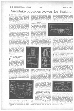
PATENT No. 617,179, comes from Albion Motors. Ltd., and E. Stead, both of South Street, Scotstoun, Glasgow, and deals with a method of obtaining braking suction from the intake of an engine.
In such schemes, the greatest degree of vacuum is obtained when the air throttle is completely closed, but if this be done, the engine will, of course, stop. The aim of the scheme shown is to enable the closed position to be approached with the certainty that the engine will not be completely starved of air.
The drawing shows an intake pipe in which the main air throttle (1) i's provided with a small by-pass passage (2) controlled by a valve (3) lightly springloaded in the open position.
In operation, all the air needed for the engine normally passes through the throttle, but when this is fully closed. the spring-loaded valve is sucked into its shut position and a high degree of vacuum is immediately available. The engine, of course, slows down preparatory to stopping, but at the last moment the suction is no longer able to keep the valve closed, and it is then opened by its spring. By this means, enough air is passed to keep the engine running at its idling speed.
IMPROVED ENGINE MOUNTING
TO absorb vibration and resist torque reaction, are the dual aims of a new method of mounting an engine shown in patent No. 617,552, by E.R.F., Ltd., and E. Sharratt, both of Sun Works, Sandbach, Cheshire.
The drawing is a transverse view of an engine mounted in a chassis in accordance with the invention. On each side of the engine is a bracket (1), which is forked to form a hinge joint about pin 2. The latter is carried by a short lever (3) pivoted on rubber bushes about pin 4. The lever is continued past this fulcrum and terminates in a rubber buffer-stop (5).
The weight of the engine tends to turn the levers and so pull the pivotpins towards each tther, and this action is resisted by compression and shear A38 stresses in the rubber bushings. When stressed in this state, the rubber is said to be capable of absorbing the vibration and taking the torque reaction. The rubber buffer-stop is used purely to limit excess movement.
A NOVO* LUBRICATING SYSTEM
A SCHEME for ensuring ft the regular lubrication of all parts of a large machine or vehicle comes in patent No. 615,746, from Tecalemit, Ltd., and C. Le Clair, both of Great West Road, Brentford, Middlesex. On a vehicle, there are some bearings which need lubricant frequently, and some only occasionally, and the object of the system is to ensure that the bearing gets its supply with regularity, whatever the period may be.
The drawing shows the essence of the system, an electrically operated control valve. Lubricant is continuously fed to port 1 and reaches space 2 under a
plunger. Compressed air enters via port 3 but is obstructed by a needlevalve (4). The valve is attached to the armature of an electro-magnet (5) which, when energized, lifts the valve and allows compressed air to reach piston 6. This moves downwards, works the plunger and ejects a charge of lubricant from the exit at the bottom, which is piped to the particular point.
Several pumping units would be used on a large vehicle, and their electromagnet windings would all be wired to a master controller, which would energize each one at its correct moment.
SUSPENSION SYSTEM FOR HEAVY VEHICLES
THE springing systern of a heavy vehicle is the subject of patent No. 617,489, which comes from the American Bantam Car Co., Butler,
Pennsylvania, U.S.A. The chief novelty appears to be the absence of the conventional type of shackle-pin.
The main suspension spring (I) has its top leaf doubled back on itself at
each end. and the ends are then tucked into a limited space on frame brackets (2). The spring bears on its upper side against a curved face (3), whilst its underside makes tight contact with a roller (4). As in many American vehicles, a " helper" spring (5) is also fitted. The spring platform is attached to the axle tube via rubber bushes.
To deal with the torque reaction, a pair of radius rods (6) is fitted; these are made in the form of stiff quarterelliptic leaf-springs having four thick blades, only one of which is visible in the drawing. The radius rods are clamped to the axle-tube at one end and bolted to a pivoted bracket (7) at the other.
A BUILT-IN JACK FOR TRACTORS
ASELF-JACKING system for a tractor is described in patent No. 616,641, by specialists in such vehicles, H. Ashfield and David Brown Tractors, Ltd., both of Meltham Mills, Huddersfield. The aim is to enable the front wheels, or those at the rear, to be raised from the ground by the power of . the tractor itself..
The chief feature is a sprag (1) which is U-shaped and extends over the full width of the vehicle. Normally it is carried in the position shown in broken line (2), but when required for use, is dropped until it reaches the ground, as shown. A pair of links (3), or preferably a pair of chains, is connected to a lever (4). The last-named member is part of the lifting tackle upon which the implement is mounted, and is provided with hydraulic cylinders. (not shown) for raising it.
_ When the leveris raised, it pulls on the chain and forces the tractor to the left, raising the front wheels in so doing. If instead of the front, the rear wheels are wanted off the ground, the tractor can be manually tipped until the rear wheels are up, and the front wheels down again. This requires little effort, because the spraks are located under the centre of gravity.