


ACETYLENE AS FUEL.
Page 22
If you've noticed an error in this article please click here to report it so we can fix it.
A Résumé of Recently Published Patent Specifications.
.Specification No. 125,308, by J. Sieber and another, both of Switzerland, has the generation and carburation of acetylene for use in automobile engines as its object.
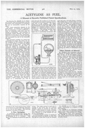
• The whole apparatus appears to be quite simple. It consists of a generator for the acetylene, a vessel containing a bath of ammonia, and what may be termed a carburetter The acetylene is generated, passes through the bath. of ammonia on its way to the carburetter, where it is heated before passing through the equivalent of a jet to the induction passages.
The generator consists of a metal box containing two trays, the lower one for the reception of the carbide, the upper one, in the surface of which are drilled small holes, for the water. A pipe leads from the generator to the bath of ammonia, which, as indicated in the drawing, is merely an inverted flask with two apertures in the stopper. a Through one aperture enters the pipe from the generator, and through the other passes that to the carburetter. The inverted flask is about half-filled with aqueous solution of ammonia, to which a small proportion of ether and camphor have been added. The gas enters by the one pipe, and bubbles through this bath of ammonia, etc., leaving by the other, and passing to an inlet at one side of the carburetter. It passes then up the innermost of a series of concentric tubes and returns through a narrow annular space inside the wall of the outer tube. The object is to cause the acetylene, which is naturally laden with small particles of liquid derived from the bath, to travel in thin layers by a comparatively long path. During this passage it is heated by conduction from the engine, and the particles of liquid are then evaporated. Thereafter the gas passes through a small nozzle very similar in design to a carburetter jet, and it emerges in the usual a along which air is drawn to mix with the acetylene on its way to the engine. For starting purposes a by-pass is arranged.
A New Springing.
A somewhat complicated spring suspension is the subject of No. 125,359, by
a. Canadian, S. L. C. Coleman. The frame of a motorcar is sunnorted upon its .ka50
axles through the medium of, in the case of each axle, two pairs of springs, one at each side of the _chassis. All these springs are Of the cantilever toe. Each pair terminates, at the butt ends of the springs, in a common casting, which is pivoted on a horizontal pin secured to the chassis. The springs diverge from one another at this point. One, the upper one, is practically horizontal; the other inclines downwards and away from the chassis, so that its outer and free end is further from the frame than the other spring, and is also much lower down. The upper or horizontal springs (one of each pair) are secured at their free ends to a kind of equalizer bar, which is merely a plain horizontal lever pivoted at.its centre to a pin on the centre of a cross member of the frame, and free to
awing. The other spring to each pair is carried to the lower pin of a. special shackle, which is secured to the axle itself. This shackle is really, perhaps, the novel part of the invention, and we have selected it as the subject for one of our illustratians.
A bobbin-shaped casting or forging. is split and slotted out inside, so that with the aid of a joint bolt it can be clamped upon the axle' and this forms a bearing. The bobbin has a double collar at each end, one of which, for convenience of erection, is loose. The shackle is mainly in two parts, one a split-sleeve which serves as a bearing, and fits upon the bobbin-shaped journal which we have described. The other is merely a depending U-shaped piece, which is bolted to this split bearing, and carries at its lower end a pin to which the outer extremity of the spring is secured. The split bearing is much narrower than the plain surface of the bobbin-like journal, and between it and the flanges of the bobbin are interposed spring washers, one on each side of the bearing. This allows certain freedom of lateral movement, which is one of the features claimed for the invention: it provides for the absorption of shocks due to glancing blows by the wheels against the kerb, skidding, the effects of centrifugal force, etc.
Other Patents of Interest.
No. 125,223 is also concerned with the springing of chassis, and is a modificalion of .Mr. G. E. D. Ralls's original patent, which has had several references in these columns. The springs are made to do duty as radius rods, their front ends being coupled to the swinging spring-controlled levers which were described as a feature of the original invention. A modification is also made in regard to the construction of the rear end of the springs, the shackle being attached to a double bell crank lever so disposed that excessive loading of the spring automatically shortens its effective length,. and increases the resistance.
Baguley Cars, Ltd., in No. 125,240, describe an arrangement of transmission whereby, by. utilizing a double clutch and two sets of _final drive bevels, a simple form of two-speed gear is obtained.
No. 125,288, by J. F. Tarns, is a spring wheel, constructed of a number of flat steel springs. No. 125;290 is an improved arrangement of the control of manually-operated lifting jacks. The patentee is C. King. Hans Renold, Ltd., have patented lin No. 125,300 an improved quick-detachable spring fastener for the coupling link of roller chains.