


ioldering, 2
Page 49
If you've noticed an error in this article please click here to report it so we can fix it.
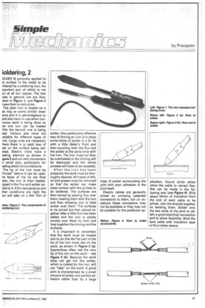
OLDER IS generally applied to le surface of the metal to be DIdered by a soldering iron, the nportant part of which is not on at all but copper. The two foes in general use are illus. ated in Figure 1, and Figure 2 -lows their construction.
The plain iron is heated on a as ring or some similar clean ame and it is advantageous to ave two irons in use when connuous work is being done so 'at one iron can be heated tale the second one is being sad. Various size irons are vailable for different types of tork. Large ones are necessary 'here there is a rapid loss of eat on the surface being solcared. Electric irons have a eating element as shown in igure 2 and are very convenient H. small jobs, particularly for laking electrical connections. The tip of the iron must be Tinned" before it can be used. he faces of the tip are filed ean, the iron is then heated, ipped in the flux and solder aplied to it. If the temperature and ther conditions are right the on will take on a thin film of
solder. One particularly effective way of tinning an iron is to place some blobs of solder in a tin lid with a little Baker's Fluid and then touching both the flux and the solder at the same time with hot iron. The iron must not then be overheated or the tinning will be destroyed and the whole process will have to be repeated.
After theiron has been prepared, the work must be thoroughly cleaned. All traces of dirt, oil and grease must be removed so that the solder can make close contact with the surface to be soldered. The surfaces are then tinned by placing flux over them, heating them with the iron and then allowing iron to feed solder over them. The surfaces to be joined are then placed together after a little flux has been added and the iron is slowly moved over them to melt and fuse together the tinning and the surfaces.
It is important to remember that the work must be heated and to do this the flat part of the tip of the iron must rest on the work, as shown in Figure 3 (a). Apprentices often rest the very tip of the iron on the work — see Figure 3 (b). Because the work does not get hot the solder, which is melted by the iron, will not "take" on the work. A good joint is characterised by a small amount of solder and perfect adhesion rather than by a large heap of solder surrounding the joint with poor adhesion in the joint itself.
Electric cables are generally joined by crimping patented connectors to them, but on occasions these connectors may not be available or they may not be suitable for the particular ap plication. Sound joints which allow the cable to remain flexible can be made in the following way (see Figure 4). Strip about 24mm of insulation from the end of each cable to be joined. Join the strands together by twisting them. Solder only the two ends of the joint to obtain a good electrical connection and to allow flexibility. Bind the bare cable with insulation tape or fit a rubber sleeve,