


THE NAPIER 2-TON COMMERCIAL VEHICLE. •
Page 16
Page 17
If you've noticed an error in this article please click here to report it so we can fix it.
A Clean, Compact Design, Without Needless Complication.
E TOOK THE opportunity recently to inspect the Vehicle that is to form the basis of Messrs.
Napier's output of commercial lorries in the forthcoming period, and we were impressed by the dominant characteristics of this production, which are its simplicity, its clear-cut design and its freedom -from all unnecessary complication.
No radical departure from what has been standard Napier practice is signalized in the present vehicle, which very much resembles the 30 cwt. chassis with which most users of commercial vehicles are already familiar. It will be remembered that as a matter of fact, the 30 cwt. lorry was designed -to carry a total gross load of 45 cwt., •including " the body. Where, therefore :the body , weighed less than 15 cwt., the ' load was correspondingly increased.
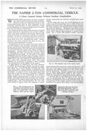
Classified as a 25-30 h.p. engine, the power unit is of the four-cylinder type, having a bore and stroke of 94 rum. and 127 mm. respectively. It will be seen from the illustration Fig. 4 that the valves are arranged all on the near side, the tappet gear being enclosed by dust-plates. Clearly shown in Fig. 4 is the method of attaching the inlet and• exhaust manifolds which are secured by four dogs. To the right of the Solex carburetter is seen the gear type oil pump, which is so arranged that the 'pump, strainer and filter may be lifted out as one unit merely by disconnecting one pipe union and removing three nuts. The crank chamber oil is poured in through a filter situated very conveniently on the offiside of the engine.
A high 'degree of eoinpression has been adopted, of which the• advantages, though not always apparent, are real. For" driving the camshaft and magneto shaft, silentchain gearing is employed, this being enclosed in a timing cover at the front end of the Motor. A glance at the water outlet pipe will show that it has the necessary continuity of upward slope, to permit of the functioning of a thermosyphon action supplementary to that of the water pump. It is quite good policy to mount the magneto on the isidelof the engine remote from the heat of the exhaust-pipe this notwithstanding the fact that some makes of engine where the magneto is iname
diately underneath the exhaust manifold give good results. '4
Of the single disc type, the clutch depends for its action upon springs pressing upon a plate or disc connected to the gear shaft, this spring pressure gripping the plate between two specially-lined surfaces rotating with the flywheel. Maximum depression of the clutch brings into action a clutch brake, by means of which useful adjunct gear-changing is greatly facilitaind. Fig. 2 shows the flexible leather universal joints interposed between the clutch and gearbox. In this view is also seen the very important greaser that lubricates the sliding surfaces of the clutch. withdrawal mechanism. Possibly, because it is generally out of sight, many drivers neglect this important greaser, with detrimental results to the clutch, of which the operation is rendered needlessly difficult. .
A general idea of the disposition of the' controls may be gained from Fig. 3, wherein are seen the , throttle and ignition levers on the steering wheel, the arrangement of the pedals, and the very .convenient location of the petrol filter which, with commendable
consideration for the convenience of the driver, has been. placed on the dashboard underneath the petrol tank.
A change-speed lover operating in a gate quadrant controls the four forward speeds whieh, with the reverse, are provided for in the gearbox. The arrangement of the change-speed lever and the brake lever is to be seen clearly in Fig. 1, from which it will be noticed that the former is outside the latter ; in other words, the brake lever is nearer to the driver's hand. This view also shows clearly the disposition of the accelerator pedal and the rods connected thereto. Of easy aCcess is the adjustable rod that has to be lengthened or shortened when it becomes necessary to alter the setting of the throttle. Another feature of the Napier lorry that is to be seen from Fig. 1 is the pro vision for greasing the springs ; spring greasers need always to be of liberal size, and in this respect the two-ton Napier vehicle is not wanting.
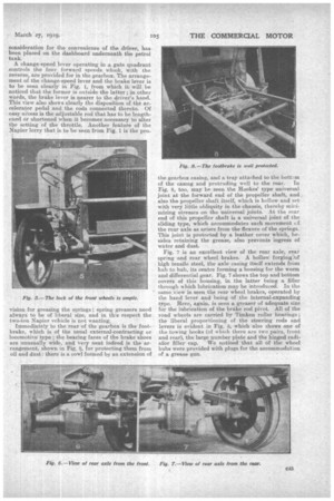
Immediately to the rear of the gearbox is the foot• brake, which is of the usual external-contracting or locomotive type; the bearing faces of the brake shoes are unusually wide, and very neat indeed is the arrangement, shown in Fig. 5, for protecting them from oil and dust : there is a cowl formed by an extension of the gearbox casing, and a tray attached to the bottcm of the casing and protruding well to the rear. In Fig. 5, too, may be seen the Hookes' type universal joint at the forward end of the propeller shaft, and also the propeller shaft itself, which is hollow and set with very little obliquity in the chassis, thereby minimizing stresses on the universal joints. At the rear end of this propeller shaft is a universal joint of the sliding type, which accommodates such movement 61 the rear axle as arises from the flexure of the springs. This joint is protected by a leather cover which, besides retaining the grease, also prevents ingress of water and dust.
Fig. 7 is an excellent view of the rear axle, rearspring and rear wheel brakes. A hollow forgi47of high tensile steel, the axle casing itself extends him hub to hub, its centre forming a housing for the worm and differential gear. Fig. 7 shows the top and bottom covers of this housing, in the latter being a filler through which lubrication may be introduced. In the same view is seen the rear wheel brakes, operated by the hand lever and being of the internal-expanding type. Here, again, is seen a greaser of adequate size Mr the lubrication of the brake rod pivot, All of the road wheels are carried by Timken roller bearings ; the liberal proportioning of the steering rods and levers is evident in Fig. 5,• which also shows one of the towing hooks (of which there are two pairs, front and rear), the large number plate and the hinged radi
atior filler cap. We noticed that all of the wheel hubs were provided with plugs for the accommodation of a grease gun.