


Patents Completed.
Page 24
If you've noticed an error in this article please click here to report it so we can fix it.
CompiLae specifications of the following patents will be sent to any address in the United Kingdom by the Sale Branch, Patent Office, Holborn, W.C., upon receipt of eightpence per copy.
A Simple Carburetter.
A. H. G. Girling, No. 3696, dated 14th February, 1912.—In this carburetter the float chamber is situated immediately beneath the air and mixture passage in which the throttle valve is
situated. A passage extends downwards about the middle of the chamber into the fuel, and this serves as the jet at its upper end. The throttle is preferably of the type shown, in which the air passage can be gradually restricted but is always immediately above the jet. The valve in the fuel passage is connected to the throttle, so that the quantities of fuel and air are kept proportional for all speeds. The throttle may be turned so as to close the jet and open an air passage at the upper side of the inlet conduit. In order to reduce the excessive flow of petrol at high speeds, two inlets are provided from the suction -conduit to the float chamber, one being on each side of the throttle. These have the effect of creating a partial vacuum above the liquid. Alternatively, an air inlet may be made in the jet passage, so that air mixes with the fuel in its passage to the jet.
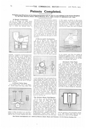
A Direct Valve Gear.
F. E. Baker, Ltd., and F. E. Baker, No. 16,214, dated 11th July, 1912.—The object of this invention is to provide a simple and direct-acting valve gear suitable for use on motor vehicles and other high-speed internal-combustion engines. An anti-friction roller is mounted in the lever which operates the valves. In fitting this roller the lever is bored out, and the roller inserted from one side. A small flange is left at the other side to limit the lateral play of the roller, and then the lower part of the lever is cut away so as to expose a sufficient part of the roller to bear on the operating cam surface. A washer is riveted on the side of the roller, and this engages the outside of the flange on the lever so that the roller is held from side play in either direction.
A Heavy-spirit Carburetter.
R. W. A. Brewer, No. 7170, dated 23rd March, 1912, cognate Application No. 13,445, dated 7th June, 1912.—In this carburetter the mixing device for the heavy fuel, which is preferably one whose boiling point is not less than 1503 C., is shown in one of the accompanying figures. An air inlet at the bottom is controlled by a floating valve which also operates a needle valve controlled by a dash-pot at its upper end. The heavy fuel enters by the upper passage
on the right-hand side, and passes downwards around the needle valve into the mixing chamber, where it mixes with the air, and is then passed through a vaporizing coil heated by the exhaust of the engine. The gasified mixture next passes to a mixing chamber shown in the large illustration on the left. Here it is mixed with a further supply of air, and passes through the throttle valve and a two-way cock, to the induction pipe on the left-hand side. The twoway cock controls a second inlet from an ordinary petrol carburetter which is used for starting up.
The British Motor Cab Starter.
M. de Jarny, and the British Motor Cab Co., Ltd., Nn. 2457, dated 30th .Tanuary, 1913.—It is stated in this specification that a mixture of paraffin and petrol, having 50 or 60 per cent, of paraffin, can be successfully used as a fuel on motor engines, the only objection being that it is difficult to start the engine when cold. The present invention describes means for starting up the engine with petrol_ A small tank, fitted on the dash-board, supplies petrol to an automatically closing valve, which is situated immediately above the inlet pipe
to the engine, as shown in the accompanying sketch. The valve is held closed by a spring and is opened by a lever at the front of the machine beside the starting handle. When it is desired to start up the engine, the valve is opened for an instant, and then the engine is immediately cranked round. The petrol supplied is sufficient to start the engine, which will then continue to run on the mixture of paraffin and petrol.
Automatic Fuel Feed.
G. Constantineseu, No. 10,037, dated 27th April, 1912.—In one construction of this device for obtaining an automatic regulation of the feed of liquid to a carburetter, the suction pipe extends upwards from the bottom of a vessel in which the liquid fuel is kept at an approximately constant level. A closefitting cover is provided with a central bell which surrounds the upstanding suction tube ; this bell communicates with the atmosphere through a small opening. When suction is applied to the central tube, the level of liquid inside the bell rises until it enters the suction tube at the top. V-notches are preferably provided as shown in the drawing. It is stated that, for a four-cylinder engine developing 20 h.p., at 1000 r.p.m., the suction tube is about 5-32nds in_ diameter, and the opening to the atmosphere about * in. The suction pipe may be controlled by a valve if it be desired.