


Patents Completed.
Page 30
If you've noticed an error in this article please click here to report it so we can fix it.
GREASE CUP. —Derr. —No. 8,750, dated 15th April, 1907.—A cup (1) has a central opening in its bottom, into which a stem (2) is loosely fitted. This stem is formed with a square head (3) and a circular flange at its base (4) adapted to bear against the inside of the bottom of the cup. In a cover (7), having a central screw-threaded opening (8), is located an adjusting screw (9). This screw is provided with a jam nut (10) by means of which the screw is set after adjustment. The screw (9) is hollow and a plunger rod (11) passes through it, and is connected to a piston (12) adapted to bear against the surface of the grease.
STEERING GEAR. — Wallis. — No. 22,598, dated 12th October, 1906.—Steering is effected by a rotatable shaft (A) having right-hand and left-hand screw threads ; this is rotated by toothed wheels (B1 connected with the steering handle. The shaft is carried in suitable bearings and has two nuts (C) on it, which are connected by rods (D) with arms (DI) on the short axles of the road wheels. It will thus be seen that rotation of the shaft (A) in either direction produces correspond• mg steering movement of both wheels.
VEHICLE WHE F.I. S .—E ston.—No. 19,137, dated 30th August, 1906.—The object of this invention is to prevent dust rising during the passage of motor vehicles over ordinary roadways. It consists of two rubber tires (B) mounted in rims (D) arranged side by side, but slightly apart, leaving a groove (C) between the rubber. A corresponding groove is also provided in the felloe (A) of the wheel. In both sides of the felloe are series of holes (E, El arranged at convenient distances apart and connected with the recess (Ci. When the vehicle is in motion, air is drawn in at the outer ends of the holes {E, E) and is discharged into the recess (C) and this serves to prevent the gathering up of dust from the roads.
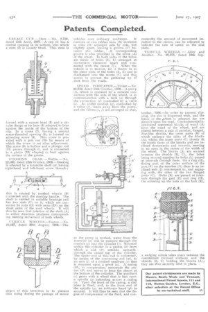
SPEED INDICATOR.—Tinker.—No. 22,812, dated 15th October, 10013.—A pump (61, which is operated by a suitable connection with the axle of the wheel, is in communication with a tank (a) through the connection (d) controlled by a valve (e). An outlet conduit {,g), controlled by a valve (f), leads away from the pump, and the valves (e, f) are arranged so that, as the pump is worked, water from the reservoir (a) will be pumped through the conduit (g) into the cylinder (j). Mounted within the cylinder is a piston (k) from which a rod (k1) extends upwards through the closed top of the cylinder. The upper end of this rod is connected, by Means of the connecting rod (se), to an arm (1) of a toothed quadrant (o) that is mounted upon a pivot" (a). A spring {45), in compression, surrounds the piston (41) and serves to keep the piston at the bottom of the cylinder. The quadrant Is) gears with a wheel that is fast upon a spindle (q) extending across a casing {r). Upon the front of the casing, a dial plate is fixed, and, to the front end of the spindle (q), an indicator hand (9,1) is secured. It will thus he seen that the degree of compression of the fluid, and con
sequently the amount of movement imparted to the piston, can be adjusted to indicate the rate of speed on the dial plate.
VEHICLE WHEELS. — Alley and Another.—No. 20,078, dated 10th Sep tember, 1906.—In order to prevent slipping, the tire is dispensed with, and the felloe of the ,wheel is adapted for use directly upon the road. Circumferentiallylaminated segmental blocks of wood (A) form the tread of the wheel, and are placed between a pair of annular, flanged, disc.:like shields, the outer parts (B) of which embrace the sides of the blocks (A), whilst the inner parts (C) closely fit the inside faces of the blocks and are inclined downwards and inwards, meeting in an apex in the centre of the width of the wheel. The blocks (Al are secured between the shields (13, C), the latter being secured together by bolts (L) passed at intervals through them. On a ring {H), fitting part of the outer surface of the part (El on the member (G) there is an inclined web (J) counterpart to, and engaging with, the other of the two flanged parts (C). Bolts (K) are passed at intervals through the part (E) and ring (H). On screwing up the nuts on the bolt (K), a, wedging action takes place between the counterpart inclined surfaces and the shields (B, C) holding the blocks (A) they are thus securely held in place.