


Trailer Independent Suspension System
Page 32
If you've noticed an error in this article please click here to report it so we can fix it.
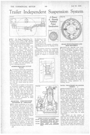
CRO!" the Eagle Engineering Co., I Ltd., and E. Collier, Eagle Works, Warwick, comes in patent No. 522,103 a design for an independent-suspension system intended for heavy trailers.
The trailer frame is provided with brackets (1) which may also be attached to a tube forming a crossmember of the frame. A cylindrical projection on each bracket forms a pivot for a swinging arm (4) carrying the stub-axle (3) for the reception of the wheel. The free end d.f the arm is connected, via a conventional shackle (2) to the lowest leaf of a quarterelliptic spring mounted in the usual manner. To prevent excessive deflection, a buffer over the swinging arm forms a limiting abutment.
• RUBBER-MOUNTED CLUTCH PLATE
ACLUTCH in which the central plate is carried upon a rubber annulus is shown in patent No.. 520,437 by C. Macbeth, 67, Norwich Union Chambers, Congreve Street, Birmingham. In the drawing the hub of the clutch carries a dished metal ring (2), to which is vulcanized a taper-section rubber ring (1). The other face of the rubber is bonded to a disc (5), which forms the clutchplate proper.
In the event of failure of the rubber an alternative coupling is provided to take over the drive. This consists of small pegs (4) riveted to the clutch plate. Normally, they are clear of slots in an oil-flinger (3), but should the rubber fail they would engage the ends of the slots and so transmit the drive.
The likelihood of failure seems remote, for the resistance to shear stress is considerable.
RELIEVING INJECTION-PUMP GOVERNOR OF VIBRATION
THE rotary oscillations of an injection-pump shaft are apt to impose a considerable thrashing action upon the governor mechanism, especially as the latter must perforce possess heavy weights moving at a fairly large radius. To filter out these oscillations is the objeCt of a friction coupling shown in patent No. 521,173 by Robert Bosch, G.m.b.H., Stuttgart, Germany.
In the drawing the injection-pump spindle (1) carries a boss fitted with a keyway at one point. The governor mechanism is connected to the outer sleeve, and the drive is transmitted by a sprung friction ring (2), engaging in
the keyway of the spindle. By this means the governor revolves at the average speed of the spindle, all sudden jolts being prevented by slipping of the ring.
This torsional vibration is practically unavoidable, because the cams are heavily loaded and the load must come off and go on in a relatively small number of degrees of camshaft rotation. BRAKE WITH STRAIGHT-LINE SHOE MOVEMENT
PATENT.. No. 522,178, from Automotive Products Co., Ltd., and G. Gates, Brock House, Langham Street, London, S.W.1, shows a brake mechanism in which the shoes move in a straight line instead of the more usual pivoting motion. In this design, a pair of spreaders (1 and 5) is employed, which may operate hydraulically or mechanically. When expanded, they cause a pair of arched bridge-pieces (4 and 6) to move outwardly. Each arch carries a setscrew (2) which presses on its shoe and forms the adjusting
member. The shoes are pivoted on cross-pins (3) which can also slide alo.ag slots in the arches.
The radial expansion of the shoes is claimed to give uniform wear, and the brake operates equally well in either direction. The lack-plate is provided with windows through which the heads of the adjusting screws can be pushed round by a screwdriver, the degree of adjustment being indicated by a clicking device.
NOVEL TWO-STROKE 01L-ENGINE DESIGN • IMPROVEMENTS in the scavenging 'system of a two-stroke oil engine form the subject of patent No. 522,001 from H. Ricardo, 21, Suffolk Street, London, S.W.1. The main object of the scheme is to prevent the back-flow of the exhaust gas when the air ports are uncovered by the descending piston.
The engine employs an overhead exhaust valve (1) whilst the air charge enters from a ring of ports (2) fed from a conduit (5). The air supply originates from a piston-pump (3) which is reciprocated by a small connecting-rod pivoted on the n am n big-end. The inlet and delivery strokes of the pump piston are controlled by a rotary valve (4), the timing of which may be made adj astable.
The object of the scheme is achieved by so timing the rotary valve that the air in the conduit (5) is trapped under pressure, and can thus overcome the exhaust pressure so soon as the ports are uncovered. Another patent, No. 521,892, also appears dealing with other details of the invention.