


New 'Foden Five-speed Gearbox
Page 22
If you've noticed an error in this article please click here to report it so we can fix it.
Compact Component Giving Direct Drive in "Top" and Having an Emergency "First" Incorporating Double-reduction Gearing
OF the various schemes for providing five speeds, the three main practices• are to use a four-speed main box in conjunction with an auxiliary twospeed gear, a five-speed box with an indirect fifth speed giving an overdrive, or a similar component having direct drive in "top " and a first speed lower than normal. With the last named certain difficulties arise, which lend special interest to a new design that has just been evolved by Fodens, Ltd., Elworth Works, Sandbach, Cheshire.
Because considerations of size and weight render it undesirable to use wheels large enough to afford in one step the desired first ratio, designers have achieved their object, in some cases, by employing simultaneously all four pairs of wheels (the normal complement of a four-speed gearbox) to afford a very low fifth, This, however, involves °considerable complexity as compared with the orthodox box.
In the new Foden gearbox a subsidiary layshaft, much shorter than the layshaft proper, is used, and is so arranged that the additional mechanism does not detract excessively from the. simplicity of the unit, whilst the increase in bulk and weight is moderate. Obviously, too, this method obviates the need for abnormally large gear, wheels.
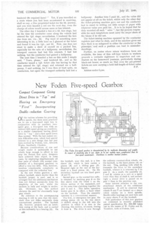
By reference to the accompanying drawing it will be seen that the mainshaft does not differ., materially from conventional practice. The layshaft (9), however, projects into an extension casing at the back, and is carried at this extremity by a bearing (5). On
the layshaft, near this end, is a free sleeve (3), which in turn carries a pinion (8) and a sliding gear (2). Mounted right at the end of the layshaft is a fixed pinion (4). On the secondary layshaft are two fixed gears (8 and 7) .
Second gear, or the normal low ratio, is obtained by meshing gear 8 on the free sleeve with the wheel 1 on the driven section of the mainshaft, and at the same time clutching together the pair 2 and 4. This latter operation makes gears, in effect, a fixed wheel on the layshaft. Thus the assembly operates in a conventional manner.
For first, or emergency low gear, the sliding pinion (2) on the free sleeve is shifted along to the left into the position in which it is seen in the drawing, this motion, of course, freeing it from 4. The drive is now through the ordinary constant-rriesh wheels, via the layshaft, to the fixed pinion (4) on the end. Thi4, meshing with wheel 6, transmits the drive to the secondary layshaft, whence it is returned by 7 to gear 2. As a result, the assembly (2, 3 and 8) rotates as a unit at a speed lawer than that of shaft 9, and accordingly a slower drive is passed on to gear I than in the previous case.
Some interest attaches to the constructional details of the. additional mechanism. It will be observed that wheels 6 and 7 are formed on a sleeve which rotates on a fixed spindle. Needle-roller bearings are used here and to carry sleeve 3 on the layshaft.
Full particulars of this new gearbox are contained in recently published patent specification No. 522,260 taken out in the names of W. Foden and E. Twernlow, both of Fodens, Ltd.