


Abridgments of Interesting Patent Specifications.
Page 18
If you've noticed an error in this article please click here to report it so we can fix it.
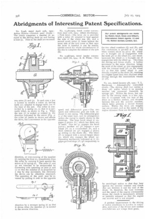
No. 8,548, dated April 20th, 190$: Arthur Downs.—Friction pawl clutch.— The clutch comprises a member (b) secured to the driving shaft (a) and having a liner (r). Free on the shaft are mounted two arms (f) and (g). In each arm a jaw is formed to receive a roller (d) having teeth (ix) adapted to engage teeth (so) in the base of the jaw. The roller is controlled by a spring (a), so that it is normally tilted, as shown in Fig. a. When the arm (I) is rocked or rotated in the direction indicated by the arrow (Fig. 2) the roller (d) jambs as shown and effects the drive, but a movement in the opposite direction, or over-running of the member (b) carrying the liner (c), immediately frees the roller by carrying it back against the action of its spring (o). The arms (f) and (g) are intended to be reciprocated by connecting rods operating on pins (i) and (j) so that the member (b) is propelled by a step by step movement, but obviously the device can be otherwise employed. The operation of the pawl may be re. versed by pulling it over in the opposite direction by a stronger spring (r) so that it drives when the member (f) is rotated in the reverse direction. No. 52,380/1905, dated (under convention) June r7th, 1904: Albert Deschamps. —Tyre lever.—The lever (A) is provided with a roller (E) adapted to bear against the side of the wheel rim (II), and a second small roller (1) bears against the inner side of the tyre cover so that once the lever is inserted it can be readily carried round the whole circumference of the rim to complete the release of the tyre
(K).
No. 7,298/1905, dated (under convention) April 7th, 1904: R. H. White.—Two
speed and differential gear.—The two speed and differential gear are both enclosed in one casing. The differential gear is of the usual type, and its arrangement within the casing is clearly shown in the drawings. The large bevel wheel (c) engages a pinion (6), which has three sets of teeth, One set (g) engages the bevel pinion ; another set (g2) engages a spur wheel (0) on a countershaft (P), and a third internal set (e) engages a pinion (g) sliding on the shafts (M). The wheel (r1) is integral with a second larger wheel (r), which also engages the wheel (q). Operating mechanism indicated at (4) engages grooved rings (r2) (ql) respectively in the two wheel members (Q) and (R), and this mechanism is pivoted at t, so that when rotated about its pivot the wheel .(rfj is brought out of engagement with the teeth (e2) on the wheel )G), and simultaneously the wheel (r) is brought out of engagement with the wheel (I). This frees the driving and driven shafts. A further movement in the same direction brings the teeth of the wheel (I) into engagement with the internal teeth (g1) on the wheel (GI so that this latter wheel is now directly coupled to the shaft (M), resulting in a higher speed than that obtained when driving through the intermediate wheels (r) (A).
No. 205, dated January 4th, 1905: T. L. Sturtevant. — Automatically controlled clutch—The driving shaft (e2) carries a drum (r6) within which is an annular member (28) connected therewith by springs (so). Within the drum, but carried by the driving shaft, is a disc (27), free to co-operate with one face of the drum as a friction surface, and situated between this and the annular member, which latter presents a second friction surface. Within the drum (i6) weights (29) are pivoted, and as the speed of the engine increases these are thrown forward
by centrifugal action so that they bear against the annular member and clutch disc (27) between it and the wail of the drum. If, therefore, the load increases and the speed of the engine consequently drops, the clutch is immediately entirely or partially released so that the engine can recover and is not stopped.
A gradual improvement in the driving of motor omnibuses in London is noticeable, and some of the drivers now neither over-lubricate nor scrape their gears.