


Combining Fluid and Cone Clutch
Page 62
If you've noticed an error in this article please click here to report it so we can fix it.
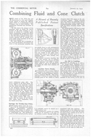
A 1:Ce3LIM& of Recently Published Patent Specifications TIIE names of the Alvis Car and Engineering Co., Ltd., and T. SmithClarke appear in patent No. 385,112, which relates to a development of the Fdttinger type of fluid coupling. The specification describes the invention as follows I
" By this means the element of the planetary train to which the driven member of the fluid coupling is connected, is rotated at a variable speed, which, consequently, modifies the action of the remainder of the planetary train, so that the driven member of the transmission gearing will be rotated at a speed which varies inversely as the slip of the fluid coupling."
The outer casing (2) is attached to the crank and flywheel, and encloses the whole of the mechanism excepting the clutch withdrawal collar (23). The driven element of the fluid clutch (5) carries with it the internally toothed ring (6), which forms the outer portion of the planetary gearing, the pinion carrier of which is formed on the end of the driven shaft (8). The sun wheel (11) is formed on the sleeve (12), which extends to a splined portion connecting with the double-coned member (18) by means of the splines (17).
The sliding member (20) grips the clutch (18) by means of the springs (22), which, when compressed, cause the clutch to be free.
Springs for Trolley-bus Poles.
FROM South Africa comes the inven
tion of R. W. Alexander, of 5, Rafel's Buildings, Johannesburg, numbered 385,028, which relates to trolleys for conducting current from overhead wires to trolley-buses, etc. The specification points out that upward-pressing springs are usually fitted to such arrangements to ensure the roller keeping in contact with the overhead wire, but such springs have to be of appreciable strength to bear the weight of the cable, consequently they cannot be relied upon to maintain contact when passing over uneven places.
The present invention describes the use of two springs, one of ordinary strength, and a second spring of much lighter character and with a longer range, which is said to be effective in preventing the roller from jumping off the cable.
Another Servo Brake..
AN interesting form of servo brake is described in the patent of E. A Rockwell, 1825, Diversey Parkway, Chicago, U.S.A., numbered 385,132. This brake, although it derives its power from the rotating parts of the vehicle to which it is attached, cannot be classed as a self-energizing type.
The arrangement consists of a casing which can be attached to the rear of an ordinary gearbox, through which an
elongated shaft (10) passes to the universal-joint flange. Freely mounted upon this shaft is an externally splined sleeve (44), upon which is mounted the friction-producing member (42), which, with its .sleeve, normally rotates with the shaft.
The sliding member (40) can be urged to compress 42 against the casing by the operation of a lever (86) and a shaft (76), and so retard its rotation in relation to the shaft. This act of relative rotation sets up movement in the threaded sleeves shown at the right of the sleeve 44, which causes the thrust bearing (66) to travel to the left, in doing which it operates the arms (110), thus causing a slight rotation of the shaft (106), to which is attached a lever (100) carrying a rod leading to the brakes in the wheels. The upper lever may operate the front-wheel brakes and the lower end the rear brakes.
The retarding effect produced by the gripping of the member 42 is not relied upon as a means for braking, but merely as a way of producing energy for the wheel brakes. The sectional view on the right is taken on the line 2.2, but the view is incomplete, as the shaft 76 should be shown in dotted lines.
An Aid to Loading.
pATENT No. 381,464, by G. Jeffery,
12, Norma Road, Waterloo, Liverpool, describes a means whereby loading can be speeded up by packing a platform with goods in the order in which they are to lie in a vehicle, then by backing the vehicle against the platform the complete load can be transferred from the platform to a lorry by setting in motion an electric motor.
A flooring of the rolling type must be installed in the lorries, to be used in
comic-atoll with this platform. The platform is also of the rolling-floor type, and should be on a level with the loadirig space of the vehicles to be used in conjunction with it.
The main features of the design lie in the fact that the platform is provided with rollers, on which it can be moved sideways, also with a turntable, both of which are provided with the object of enabling the platform to be adjusted so that it is exactly opposite the end of the lorry before the load is transferred. The view on the left is an end of the Platform; on the right is a side view.