


SOME NEW VALVE-OPERATING GEARS.
Page 30
If you've noticed an error in this article please click here to report it so we can fix it.
A Résumé of Recently Published Patent Specifications.
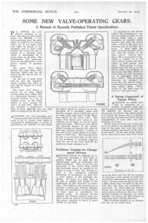
PA.POPPE, the rail . known designer of en. glues, describes in hie sped& catien No. 226,342, a new valve-operating gear, the naaiu object of which is to actuate valves set at an angle with each .other by means of .onn. camshaft, and to leave room between the valves for the insertion of a sparking plug, which is surrounded by a water space on all sides. The specification lays particular stress on the importance of the proper cooling of sparking pings. Theripper view shows plainly, the very large eadve openings which can be obtained by the use of this arrangement.
• On the left in both views be will seen th c e amshaft, which operates the valve on that side by means of a rocking lever. The lower view shows a second set of cams, which operate pall bars, which slide iii a horizontal direction aud transmit motion to a set of rocking levers on the right. which, in turn, operate the -valves on that side. This design provides a symmetrical formof head, although only one camshaft is employed for all the valves.
ANOTHER new valve-operating gear appears under the equally we-knoun name of M. S. Napier,. with whom i.s associated G. Shakespeare, of Acton, in specification No. 226,442. In this design the object aimed at appears to be the provision of a camshaft which will directly actuate valves which are set at an angle with each other in the direction shown in the lower view. The upper view shows four valves in one cylinder, all of which are set at angles with each other. The lower view shows the essential feature of the patent, which consists of forming the cams so that they always present a surface to the ends of the ;valves which is at right: angles to their axes. The tapering form of cam is so arranged that at all parts of its periphery it contacts correctly with the end of the valve stem the mushroom heed attached to it.
Toothless Gearing for Change;. speed Devices. SPECIFICATION No. 225,264 (C. R. Garrard) describes a new form of gearing which can be used for the change-speed gears of motorcars and other machinery. Were it not for our knowledge of the source from which this invention comes, we should be inclined to pass it over, but, having regard to the inventor's practical knowledge of mechanics, we here give a brief outline of the principle employed. We hope, at a later date, to be able to publish full details of the application of this invention to motorcars. The object of the invention is to provide a silent and efficient adhesion between the peripheries of discs similar to those used as gearwheels, but without teeth. In ordinary eircuinetances the friction between such surfaces would be useless for transmitting the power required to drive a motor vehicle of any kind As described in the specification, the arrangement consists of a disc or roller on the driving shaft, with a plain periphery of suitable width. Against this runs the driven roller, which in the case of a reducing gear is of larger diameter. A third ratter (an idler) is placed parallel and in line with the centres of the other rollers. Around these three rollers is mounted a ring, which is pushed on to the outer rollers, causing the three rollers to bind against each other. When power is transmitted from the driver to the driven Teener, any tendency to slip causes the ring which -enciecles them to move its centre Out of alignment with the three rollers. This movement increases the pressure between the ring and the rollere, and "thereby prevents any slipping taking place. There would be one such train of gears for each gear ratio.
A Spring Composed of Square Wires. A SPRING in which each
of leaf is composed a
A SPRING in which each
of leaf is composed a
number of square wires laid side by side is described in specification No. 204,710 (P. Savoys and A. Marguerite, of Paris). The object stated is to reduce the danger due to a broken leaf, and the speeification points out the improbability of more than one wirer . breaking at a time.
All the wires are bent over at the end,
• so as to embrace the shackle nin in the case of the main leaf, and thus independent endways movement of the wires is Prevented. In the case of the shorter leaves, they are in some cases bent round
asin the main leaf, but, for the purpose of receiving se aia bolt, merely provided for me ca preventing independent movement end ways. In some all the leaves have h
a kink were they are held by the central clip, and thus end movement is prevented. In other cases the shorter leavee are formed by bending certain wires round as shown in the lower view.
Several meth m
methods of clamping the wires together are shown, for the purpose of increasing their rigidity sideways.
The inventors suggest as an alternative the use of round wires.