


THE NEW HALLEY CHASSIS.
Page 27
Page 28
Page 29
If you've noticed an error in this article please click here to report it so we can fix it.
An Interesting Model with a Six-cylindered Engine, Four-speed and Reverse Gearbox, and a Worm-driven Rear Axle Incorporating the New David Brown F.J. Type Worm Gear.
AS WE HAVE pointed out recently on several occasions, there, is still . ample scope for improvement in the design Of both light and heavy commercialvehicle chassis. Simplicity, and the reduction of unnecessary parts are essential if British manufacturers wish to compete with foreign importations.
One of the best and most straightforwardly designed chassis which we have seen up to the present is the new sixcylindered, 3i-ton Halley. In this vehicle 'simplicity and efficiency have been keynotes in the design, whilst apart from these the machine has a very fine appearance and looks a real engineering job. Those few parts such as the crank. shaft and the worm gearing, which axe not made in the company's own works, have been obtained from makers with world-wide reputations; for instance, the crankshaft forging, which is of nickel-chrome steel, is procured from Vickers, Ltd., and the worm gearing is the now famous F.J. type manufactured by David Brown and SOY% (Huddersfield), Ltd., which gave such remarkable efficiency results when tested recently by the National Physical Laboratory. Two models are being.etandardized, but the -chassis are the same except for the wheelbeses.
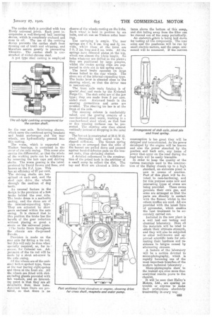
The six-cylindered engine has its ey iirlfIRTS east in threes. All the valves are on the near ride and are covered in by two plates fitted with knurled thumb screws. So high was the efficiency of this engine under test that the diameter of the valves had to be reduced in order to make the engine self-governing at over the normal running speeds by causing wire-drawing of the mixture within the cylinders. The maximum power is developed at 1,250 r.p.m.; after this speed
there is a. quick drop of the power curve.
This method of governing the engine is becoming very popular, as it is simple and'at the same time dispenses with expensive governor mechanism, which is liable to be tampered with by the driver.
The cylinder heads are separate, and that attention has been paid to detail is shown by the provision of small Inge at, each side of the cylinder head casting. These Jugs can be tapped with a lead hammer in order to facilitate removal of the casting. In some engines built on this principle, for the sake of appearance, the heads are very carefully made flush with the cylinders, with the result that, in order to break the joint between them, chisels have sometimes to be inserted, and consequently the coppereiehestos gaskets are ruined.
The valves are case-hardened nickel steel working in phosphor-bronze guides. The ;tappets are slightly offset, and are free to turn so that wear on them is not confined to one • spot, and thus pitting is avoided. The tappet, actually rotates while working.
A Coventry silent chain is used for driving the timing gears. A cross shaft driven by skew gearing drives the centrifugal water pump at the near side, and the magneto at the off side. A point in the design is that the water pump has a gunmetal spindle and also a gunmetal rotor working in, a case of the same material. Illy using similar material throughout, corrosion through electrolytic action is avoided. Both the magneto and the water pump are driven through laminated steel spring couplings, and the magneto is in addition provided with a vernier adjustment.
We have already mentioned that the crankshaft is a niael.ehrome forging. It is of the three-bearing type, the bearings being of die-east white metal. It is not weakened in any way by drilling, as the oiling system is of a, special type, in which one pipe conveys the oil to channels provided in the crankcase; by these channels it is led to wells at the tops of th3 three main bearings and also to those, of the camshaft. It then runs into
big-esel troughs. • The oil pump is of the gear type. It is situated in the sump and is driven from the camshaft by skew gearing., Effective measures are taken to prevent the circulation of dirt with the oil, and at each circuit it, passes through two filters. A small spring-16arled plunger rises and actuates a vertical rod on the dash when the oil pressure is satisfactory, The pistons are of the well-known Ricardo type, constructed of aluminium alloy. The gudgeon pins float in both the pistons and the small-ends. For the big-ends compound shims are employed ; these are half-solid metal and half strips of metal .002 in. thick, the strips being soft-soldered together. For adjustment purposes the thin strips can be removed one by one by means of a pocket-knife. Most careful attention has been paid to the question of fealaece. The connecting rods net only all weigh the same, but they are also balanced at each end. This care also applies to the crankshaft, pistons, and flywheel.
The petrol is led to a Zenith carburetter from a 24. gallon tank situated under the driver's seat, The carburetter is provided with a variable hotair intake, and the inlet, pipe from it, to the engine has an exhaust jacket, the flow of exhaust gas to which is regulated by an adjustable by-pass in the Plihau.st manifold.
The fan is supported by a 'spring-loaded pillar, so that the V fan belt never requires 'adjustment, as wear is automatically taken up by the spring, which, incidentally, rs heavy enough to prevent chatter. The fan itself is supported on ball races, and has a small friction, clutch between it, and the pulley. This 6lutch is nstrucof simple construction, and axle. consists of a spring-held
leather washer. It has the advantage of preventing cracking of the• blades at their bases, .owing to rapid changes in engine speed, and In the event of the radiator being pi essed on to the fan, owing to an accident, the fan merely stops and does not cut tubes.
With the fan pulley on the end of the crankshaft is incorporated a dynamo driving pulley, also of the V type, and a bracket is provided on the crankcase for the dynamo. Both the top and bottom half Of the crankcase are of aluminium, and the whole engine presents a remarkably clean appearance, as there are no exterior oil pipes or joints, and when it is required to move the engine from the chassis it is unnecessary to break any fluid joints except the water connections and the petrol pipe. The oil level gauge is of very simple construction. rt consists of a steel rod, on which is marked the maximum and minimum levels.
We examined an engine which was 'lamming beautifully steadily against a Fronde water brake at 1,240 r.p.m., and practically no vibration was perceptible, proving how. well the engine has been qesigned and balanced.
The engine is supported on a channelsteel sub-frame, which is flexible enough to prevent distortion of the crankcase arms owing to frame flexion. The frame itself is very, strongly constructed with two rolled channel aide members, 5 ins. by 2i ins., which are perfectly straight both in the horizontal and vertical planes. The side membera are arranged, with the channels facing outwards. This method of construction renders the cross members more accessible and enables the frame bolts to be inspected periodically for slackness. The dumbirons are carried well back into the channels and are bolted to both the flanges and the web. There are four cast-steel webbed cross members and two tubular type ; the latter carry the gearbox. All these cross members are held in position by fitted bolts in lieu of rivets—which are generally unsatisfactory.
The radiator is of the cast header and bottom tank type with a centre consiating of 5-16 in. round gilled tubes and supported on trunnion bearings at each side. An enamel name-plate is let into the-header and is held 1T1 position hy spring ring, and prevented from turning by means of a small stop. The effect is admirable.
The starting handle is carried on the front cross member, and as the sub-frame by which the engine is supported is . bolted to this cross member the starting handle is kept always in line with the does on the crankshaft.
The clutch consists of a single steel plate running dry between two Ferado rings. Its three springs are contained in sockets equally spared round the clutch cover plate. The front end of the clutch
052
shaft is supported in a Skefko bearing. The clutch withdrawal gear is of the direct type, and a clutch brake is provided. The clutch pedal is adjustable to fouldifferent positions. Between the clutch and the gearbox are two Hardy flexible fabric joists, connected by .a star
piece, which, in the long wheelbase model, is replaced by a short propeller shaft.
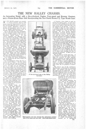
The gearbox, which is of a very clean and compact design; gives four speeds forward and a reverse. All the gears are of the straight-tooth type and are mounted on plira d shafts. The first-motion shaft is supported on two Timken bearings, as also is the third-motion shaft, the forward spigot end of which is supported in a small Hoffmann taller bearing in the end of the first-motion shaft. It is thus use to slide slightly to allow for expansion of the shaft. The Timken bearings are themselves supported in semi steel. liners. The lid of the gearbox is provided with a breather. The gearboic is slung at three Points from the tubular cross members, to which we have already referred; at each point it is held by caps.
The selector forks are screwed on to the selector rods and locked in position by split-pinned 'nuts. The forks them:elves are also split across the threads and locked on to the roes by bolts.
A neat device is a mileometer, which is carried on a biacket projecting from the gearbox casing, and driven by a worm eat on the second-motion shaft.
Care has been ttken to render the gearbox easily accessible for replacements, arid all the shafts and gears can be withdrawn without dropping the box.
The change-speLd mechanism is of the subsidy type. The gate is carried by a bracket boitsd to the frame, together with the brake quadrant, but as the connections between the lever and the gearbox are universally jointed, no stresses can be transmitted to the latter, so that the mechanism cannot bind owing to frame flexion. The cardan shaft is provided -with two Hardy universal joints. Each joint incorporates a well-designed ball centring device, which is completely enclosed and runs in oil. The use of the centring device prevents the cardan shaft from running out of truth and whipping, and -therefore assists greatly inpreventing vibration. The cardan shaft is constrated of nickel-chrome steel.
A pat type steel casting is employed
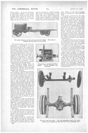
for the rear axle, Reinforcing sleeves, Which carry the combined spring brackets and brake anchorages and the rear *heels, are hydraulically pressed into this casting.
The worm, which -is supported on Timken bearings, is contained in the cover of the axle casing. This cover also carries the differential, so that the whole of the working parts can be withdrawn by removing the hub caps and driving shafts. The worm gearing is the latest praduced by David Brown and Sons, and known as the F.J. type. This has an effiCieficy of 97 per cent. The driving shafts are tensplined at each end, and the steel caps drive the wheels through the medium of dog teeth.
An unu.sual feature in the design is the provision (d a foot brake behind the rear axle. The brake drum is a malleable casting, and. the shoes are of the internal-expanding type. They are actuated by skew gears enclosed within the axle casing. It is claimed. that in this position the brake has the benefit of the gear reduction without placing so great a strain on the universal joints.
The brake liners throughout the chassis are die-pressed Ferodo.
Provision is made on the rear axle forfitting a tie rod, but this will only be done when specially required, as, for in
/seance, for Colonial use. Adjustment of the tie rod will be made by a stout set-screw in the axle easing.
All the wheels are of the cadsteel hollow-spoked type, those at the rear baying eight spokes and those at-the front six. All the wheels are fitted with dirtexcluding glands provided with felt washers, and an interesting point is that they are all detachable from their hubs. Anti-rust brass liners are provided, so that.. there is no chance of the wheels rusting on the hubs. Each wheel is held in poSition by six bolts, and all run on. Timken roller bearngs.
The springing is ample. The rear springs are 4ft. 6 ins long and 31 ins. wide, whilst those at thefront are 3 ft. 3 ins. long and 3 ins. wide. All the springs have rebound plates at the top, which run almost the whole length. No holes whatever are drilled in the plates; they are positioned by large pimples, whilst the centre spring clips are supported in slots cut in the sprmg seats. The hand brake operates on large drums bolted to the, rear wheels. The shoes are of the internal-expanding type. The brake lever its sibeated dose to the steering wheel, so that the driver uses it instinctively.
The front axLe main forging is of special steel and made by the Kirkstell Forge Co, The stub axles are of the jaw type; they arc made from 3 per cent, nick-el /steel. Awkward bends in the steering connections and arms are avoided. The steering tie bar is at the front of the axle.
The steering column is comfortably raked, and the gearing consists of a case-hardened steel worm, working in a ease-hardened steel wheel, so that lour or five wearing surfaces can be presented. The steering arm rises almost vertically instead of dropping in the usual way.
The bonnet is constrected of 26 S.W.G. steel, thoroughly well stayed with Vshaped stiffeners. The bonnet spring clips are so arranged that the sides of the bonnet are pulled down and pressed against bonded-asbestos pads on the bonnet rests, thus obviating chatter.
A detailed refinement in the construction, of the petrol tank is the addition of a small sumn to collect the dirt. The tap and filter are situated a little dis tance above the bottom of this sump, and dirt falling away from the filter can be cleaned out of the sump periodically. An da,borateApla,nt is being laid down for testing all the components. The rear axles and the gearboxes will be run by small electric motors, and the amps. consumed will be measured.. If the current
consumption is too great they will be stripped and reconstructed. As the power developed by the engine will be known and also the power absorbed by the gearbox and back axle, any losses of power that occur on the road during tho road tests will be easily traceable. In order to keep the quality of the various materials used in the construction of the Halley chassis up to a high standard, an elaborate plant is now in course of erection. Pert of this plant will be devoted to case-hardening, and for this purpose some new and interesting types of ovens are being provided. These ovens generate their own gas, and some are arranged se that the parts are directly in contact with the flames; whilst in. the others muffles are used. All are Provided with the latest form of pyrometer, which enables the heat treatment to be accurately carried out.
Included in the new plant is a well laid out testing and chemical laboratory. Here all the materials will be tried to obtain their ultimate strength, and they will also be subjected to other well-known and approved scientific tests for estimating their hardness and resistance to fatigue caused by alternating stresses.
A feature of the laboratory will be a section devoted to micro-photography, which is rapidly becoming one of the motet important branches of the modern technical laboratory .
Micro-photographs show. to the trained eye even more than analytical results prove to the chemist.
It will be seen that Halley's Motors, Ltd., are sparing no trouble or expense to make their productions absolutely trustworthy in evtry way.