


Two-stage Pressure charging System
Page 36
If you've noticed an error in this article please click here to report it so we can fix it.
A Resume, of Patent Specifications That Have Recently Been Published
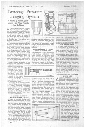
A PRESSURE-CHARGED engine,. .1-1 shown in patent No. 542,357 is said to be particularly suitable for two purposes—aircraft when in ratified atmosphere, and vehicles driven by gas of low calorific value. A scheme of this nature may well be the solutrou of the poor performance of engines driven by producer gas. The patentee is C. Kjellberg, Stockholm.
The system is described as applied to a two-cylindered two-stroke, the performance of which would be equal to a four-cylindered engine of conventional type. Actually, three cylinders in line are used, one (1) functioning as a charging pump for the others, which are the working. cylinders. Precompression of the charge is carried out in two stages; the in-line pump (1) (which is , double-acting) gives an initial compression, whilst the second stage is performed by a small cylinder (2) on the side of the engine, driven at twice crankshaft speed.
Gas-air mixture is supplied to the first pump, and the timing is arranged so that the end of the compression stroke of the first pump coincides with the beginning of the compression of the second pump, in order that a transfer may. occur. After being recompressed, the mixture is passed to the engine Should it be required to start on petrol, the first compression is by-passed, and the mixture is fed to the second pump direct.
Scavenging of the working cylinders is effected independently of the pumping system, crankcase compression being employed in the customary manner, the air entering via passages (3) in ale castitg. To control the admission of the charge to the combustion spaces there is a rotary sleeve valve (4) in Cylinder (2).
TO LIGHTEN FRAMES OF HORIZONTAL-RAM TIPPERS WHEN an hydraulic tipping ram is VV lying nearly horizontal, its initial movement exerts a considerable stretching force on the surrounding framework, and this usually necessitates the provision of heavy longitudinal members to withstand the stress. To avoid the need for this special strengthening is the object of a tipping-gear design shown in patent No. 541,926 by Sunsaloon Bodies, Ltd., and D. .Pearson, both of Weston Works, Birmingham.
In an accompanying drawing is seen a plan of the scheme, which employs a pair Of tie-rods (2) to unite the ram
.. head 4110i-tier .(a), to the pivot axis (1) of the tipping body.' The horizontal
stresses are thus restricted to 'this selfcontained structure, and are not transmitted to the chassis, which has then to deal with only the vertical loading. The saving in unproductive weight brought about by thc absence of heavy longitudinals is claimed to he considerable.
BONDED RUBBER IN " CUSHDRIVE " CLUTCH DISC PREVENTION of the 'transmission of torsional oscillations, whilst giVing resiliency to the drive, is the object of an improved design of clutch plate shown in patent No. 542,407 by the Borg and Beck -Co, Ltd., Tachbrook Road, , Leamington Spa. We illustrate one example of the design.
In this the fabric-carrying disc (5) is of thin spring steel about 0.02 in. thick, instead of the more usual 0,06 in. This disc, although centred on the hub (4), is not rigidly fixed thereto, the rivets (3) passing through slots in the disc to permit a limited peripheral freedom. The actual torque. is transmitted via a further disc (2) and a soft rubber ring (1), bonded with disc 5 into a resilient member.
Normally, . the working torque imposes a moderate shear stress on the rubber, but 'abnormal overloads might cause damage. To prevent this, ,the rivets (3) act as a safety drive, reaching the ends of their slots when the rubber is stressed to its maximum safe A certain amount of friction between the rivet-washers and the plate serves to damp out any forsional oscillation that may arise.
INJECTOR NOZZLE GIVING RING AND RADIAL SPRAY
Tobtain a fine, mist-spray in the neighbourhood of the nozzle, combined with long-distance spurts to reach the farthest parts.of the cylinder, • -is the object of ,a design of injector shown in patent No. .542,371 by S.A. ,Adolphe Saurer, Arbon, Switzerland.
An accompanying illustration depicts the tip of the nozzle on an enlarged scale; in this, a conical-backed pintle .(2) seats on the body, and forms both an admisSion valve and an 'atomizer. From most bf the seating a fine annular spray is obtained, but a series of notches (1) in the seating causes a local thickening of the spray to form jets of fuel of greater penetrating power. In another design, the seating is uninterrupted, the notches being cut in the back face of the valve.
SKIN-STRESSING TO LENGTHEN SPRING LIFE• A MANUFACTURING process for
• CI leaf springs, claimed to give them a longer life and a greater load-carrying capacity, is shown in patent No. 542,043 by the Eaton Manufacturing Co., Cleveland, Ohio, U.S.A.
This concern proposes to treat the tension side of the leaves by highvelocity bombardment with hard steel shot. An important feature' of the scheme is that only orie side of the leaf is thus treated, the theory being that the metal on this side is pre-compressed by the hammering to a tensile stress of 10,000 lb. per sq. in. When the load is applied, it is first opposed by this self-contained stress, and only the load in excess of this value has to he resisted, by the bulk of the blade. The treatment is claimed to prolong the life of the blade by at least 60 per cent.
It is interesting to' note that this pre-stressing method has for many years been used in the manufacture of guns; in this case, an initial crushing stress is applied by \virewinding, and the barrel has to
ithstand only the bursting stress in excess of the applied crushing force.