


ANOTHER INTERNALCOMBUSTION TURBINE.
Page 28
If you've noticed an error in this article please click here to report it so we can fix it.
A Résumé of Recently Published Patents.
ANOTHER internal-combustion turbine is described in specification No. 170,589, by Dr. Lug. H. Fottinger. In this, as in the one described in these columns a fortnight ago, a fluid medium is interposed between the hot gases and the, moving parts of the device, the principal difference between the two being that, in the present one the moving column of water, which, in the one previously .described, served as pistons for the explosion cylinders, is now the equivalent of a fluid rotor for the turbine.
The inventor relies for his effects on the principle which is diagrammatically illustrated by one of the two drawings from the patent specification, which we reproduce on this page, and which may briefly be stated as follows. Under certain conditions rotation of a liquid within a stationary working space, resulting in a cylindrical or conical inner level and a hollow space within this inner level, may be produced by the kinetic energy possessed by the entering liquid. If, for instance, referring to the figure, water is caused to flow tangentially into a funnel or cylinder-like stationary vessel, the tangential velocity will increase as the liquid approaches the smallest diameter of the vessel, and a hose-like cavity will be formed in the centre. The law governing the peripheral velocities of the moving liquid is of the form vr = constant, v being the tangential velocity and r the radius from, the centre of the chamber to the moving particle of water which is being considered.
Now, in the turbine which is proposed by this inventor, the central hollow in such a vortex forms the working cylinder of the explosion engine. If it be imagined that the hollow is filled with a combustible mixture, which is then exploded, the pressure within the chamber will increase, and the velocity of the departing water will be caused to increase considerably, thus enlarging the chamber. The water which is driven out. at high velocity is conveyed to a hydraulie turbine, where it performs usetul work. At the same time, of course, the hollow cavity is enlarged, and, suitable valves operating, permit the burnt gases to escape, at the same time admitting a. fresh supply of scavenging air and combustible mixture. The pressure within the hollow water chamlaor being released, it tends to contract once more to its former sire, thus compressing the gases, which are fired at a convenient instant by orthodox .means, reproducing the cycle of operations which we have 'just described.
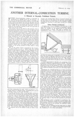
In actual practice the water, or moving fluid, revolves in a closed circuit, rebentering the working chamber again after it, has done work in the hydraulic turbine, and a practical example of a suitable construction, which will permit of this taking place, is illustrated by the Second drawing. In this coustruction water is constantly flowing in at the central pipe, as indicated by the arrow. It is guided to the outside-of the cylindrical chamber by suitable vanes, where it whirls round at a great pace, forming a vortex with central hello* chamber, as has been described. The internal-combustion cycle proceeds within that chamber, the varying size of which, during compression and after explosion, is indieated by the dimension. lines. The revolving water passes from the vortex chamber at the opposite end of the turbine to that at which it has
B44 entered, and, leaving there with an increased velocity, premed upon it as the result of the explosion, travels along the pipe, shown in dotted lines, to the ,hydraulic turbine, subsequently returning, to pass again through the working turbine.
Other Patents_of Interest.
A tipping gear which is designed to lift the body of the lorry with its load, as well as to tip it, is described in specification No. 196,601, by the famous firm of Fried Krupp Aktiengesellschaft of Essen. The body is mounted on a supplementary frame, which is hinged near its front end, and when the tipping gear is operated to lift the front of the body, by means of telescopic differential screws, this supplementary frame also lifts the rear end of the body, but not so much as the front end is lifted by the screw. The arrangement and one of the uses of the gear are shown on one of our illustrations.
A detail improvement in Bowden wire mechanism is described by J. Doherty in specification No. 191,547. The prin. cipal feature is the provision for adjustment of the means of retaining the lever in any position in which it may be fixed, which means takes the form of intermeshing grooved discs, one of which is attached to the lever, the other being immovable.
Specification No. 191,543 describes one of those interesting change-speed gears in which the variation in gear ratio is controlled by a swinging or rotating 'mass, termed an inertia memlber, which is so mounted between the 'primary and secondary transmission members that it is caused to oscillate at a rate which is proportional to the difference beween the speeds of those two members. (W. Hunt.)
The rubber band tyre which is patented in specification No. 191,545, by E. B. Killen, appears to be in some ways a development of the well-known N.A.P. tyre, with -which the same inventor was connected. In this band. tyre the metal base is to all intents and purposes in two parts, separated by a short distance piece, thus allowing the central portion of the tyre a certain amount of freedom to collapse under stress. The same ptinciple of providing that the area of tyre in contact with the road varies more or less in -proportion to the load which is being carried is maintained he...e as in former inventions by Mr. Killen. The lubricating device for leaf springs, which is the subject of patent specification No. 191,554, by A. E. A. Davies, is of the type in which a screw-operated wedge is forced between the leaves. of the spring so as to separate them, as a pre-' liminary to injecting the lubricant. The SaIlle device which peeforms this service also injects the lubricant from a cup which is part and parcel of it, through a passage formed in the opening wedge, so that the dual operation is performed in one.
The splashguard which is described in specification No. 191,577, by J. Henderson, consists of a strip of rubber with i brush attached, mounted n a frame which is suspended from the hub of the wheel on ball bearings, the suspension means consisting of coil springs. . A simple means of retaining the foot, brake lever of a Ford or other car in the " en " position is described in specification No. 191,595, by F. M. D. Hart and another.