


Novel Approad o Air Suspension
Page 32
Page 33
Page 34
If you've noticed an error in this article please click here to report it so we can fix it.
AIR suspension is very much in the news and particular emphasis has in recent months been placed on the advances that are being made on the Continent. In the report of the Turin Motor Show (November 8, 1957) brief mention was made of the new Saga Elipress unit, which was exhibited on the Pirelli stand.
Further details of this spring are now available, together with information on the use of Firestone-type suspension units in various German and Italian goods and passenger vehicles. All this information has been supplied by Saga, of Milan, who, in addition to developing the Elipress spring, are concerned with the production and sale of the Firestone Airide bellowstype units. These are known in Italy as Torpress or Ropress, according to whether their application is for commercial vehicles or private cars.
Basically, the Saga Elipress spring is an air-filled version of the Eligo unit. This has been employed successfully for a number of years on railway rolling stock and trams, including the American P.C.C. tram mentioned in the description of the D.C. Transit System, Inc., of Washington (The Commercial Motor, August 23, 1957).
Rubber and Steel Spring
The Eligo spring consists of a rubber tube with helically f or med walls embedded in which is a helical coil spring. The steel and rubber components of the spring complement each other to provide excellent suspension characteristics and greatly improved life.
By endowing the unit with stability the steel coil prevents the rubber from being over-stressed in a horizontal plane and gives greater loading capacity than is possible with a rubber spring of comparable size, thereby avoiding the danger of excessive stress from over-compression of the rubber.
The rubber section of the spring gives the Eligo unit an elastic hysteresis unlike that obtainable with a conventional steel coil spring, and it is variable within certain limits according to particular design requirements.
Furthermore, the rubber helps the steel spring in that it reduces the stress to which it is subjected and increases its durability by damping the vibration frequency of the coil spring; reduces the.dynamic stress peaks and provides a variable rate; and, by acting as a chemically inert layer on the surface of the coil, forms a protection against superficial corrosion, one of the main causes of spring breakage.
A3() Another important advantage of the effect of rubber on a steel spring is that the transmission of high frequency acoustic and mechanical vibration is eliminated, thus the spring acts as an excellent insulator between the sprung and unsprung masses of a vehicle.
Although the Eligo spring has a variable rate, it suffers a disadvantage when compared with air-suspension systems, in that a constant loading height is not obtained. Furthermore, because the rubber " coils" tend to combine and are
constant -pressure conditions. subject to heavy compression stresses under full load, large spring deflections under such conditions cannot be obtained.
By making the Eligo spring air-tight, however, and using it in a way similar to that employed in a conventional airsuspension system, these remaining disadvantages can be eliminated and fully variab:e-rate suspension can be obtained without increase in travel.
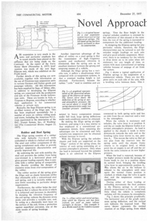
With the Elipress spring the unladen chassis and body are supported on the " Eligo" section of the spring alone, the interior of each spring containing air at normal atmospheric pressure. Only when the load is increased beyond the unladen figure is air admitted to the Elipress springs. Thus the floor height in the original unladen condition is retained by the admission of this air-and at the same time the rate of the spring is increased to compensate for the additional loading.
In designing the Elipress spring for any particular vehicle, therefore, the Eligo characteristics can be tailored to suit the unladen weight loadings on each axle and give good unladen suspension. Moreover, there is no tendency for the vehicle to drop down on to its axles when left stationary for any length of time, as occurs with most conventional air-sprung vehicles because of seepage of air from the system.
Fig. 1 shows a typical application of Elipress springs to the suspension of a commercial vehicle. There arc two Elipress units on each side of the axle, with a levelling valve between them. This i$ connected to both spring units and has an inlet from the air reservoir and a vent to the atmosphere.
When the vehicle is stationary and unladen, the valve lever is at position A and the air inside the Elipress bodies is at normal atmospheric pressure. As load is applied. to the chassis it tends to move downwards towards the axle and so the levelling valve lever moves to, say, position A,. This moves the valve so that air can pass from the reservoir into the spring units until the chassis frame returns to its original level, at which point the air supply is cut off and the air inside the units remains at its new higher pressure.
When the load is removed, because of the higher pressure inside the springs, the frame tends to rise to a position above its normal level, bringing the levelling valve lever to approximately position A2. This allows the air in the bellows to exhaust to the atmosphere until once again the normal frame position is reached, at which stage the valve is again shut and the suspension remains in equilibrium.
During either of these loading or unloading movements the final pressure in the Elipress springs is, of course, ,directly proportional to the imposed load. Only when the vehicle is completely unladen will this pressure be atmospheric.
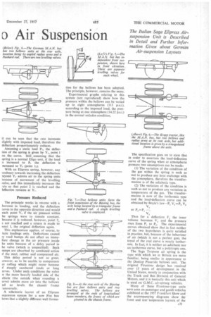
Fig. 2 shows this principle graphically. The horizontal axis of the graph represents spring deflection, and the vertical axis indicates the imposed load. The curve "shown represents the normal reaction of an Eligo spring, from which it can be seen that the rate increases ;lightly with imposed load, therefore the deflection proportionately reduces.
Assuming a static load P, the deflection of the spring is given by Y, point 1 on the curve. Still ,assuming that the spring is a normal Eligo unit, if the load s increased to 1K, the deflection is ncrcased to Atr (point With an Elipress spring, however, any tendency towards increasing the deflection )eyond Y„ admits air to the spring units because of movement of the levelling valve, and this immediately increases the .ate so that point 2 is reached and the leflection remains at Y.
Pressure Reduced
The principle works in reverse with a lecrease in loading, and the deflection [loves in the opposite direction and would each point Y„ if the air pressure within he springs were to remain constant. 3ecause it is reduced, however, point 2, s not reached and a return is made to point I, the original deflection again.
This explanation applies, of course, to tatic loadings only. Deflections caused iy road bumps do not effect an imme!late change in the air pressure inside he units because of a delay period in he valve (which is unspecified), Such iumps are absorbed by combined action if the steel, rubber and compressed air.
This delay period is not so great, towever, as to be unable to compensate or rolling which might occur because .f steeply cambered roads or long urves. Under such conditions the valve n the more heavily loaded side of the ehicle (the outside when rounding a urve) admits more air into the bellows nd so levels the chassis frame -ansversely.
A schematic layout of an Elipress uspension system for a new Fiat bus bows that a slightly different wall forma lion for the bellows has been adopted. The principle, however, remains the same.
Experimental graphs relating to this system (not reproduced) show how the pressure within the bellows can be varied up to eight atmospheres (113 p.s.i.), according to the imposed load, the pressure being at one atmosphere (14.22 p.s.i.) in the normal unladen condition. The specification goes on to state that in order to ascertain the load-deflection curve of the spring when at atmospheric pressure two assumptions can be made: (1) The variation of the condition of the gas within the spring is such as not to produce any heat exchange with the atmosphere, therefore the transformation is of the adiabatic type.
(2) The variation of the condition is
such as not to produce any variation in temperature of the gas. The transformation is now of the isothermic type and the load-deflection curve can be obtained by Boyle's law—P, V,=-P., V,
V,
or P2=P,
V,
Thus for a deflection F. the inner volume becomes V, and the pressure rises from P, to P. The experimental curves obtained show that in fact neither of the two hypotheses is quite satisfied in practice, but, because of the behaviour of air (which is not a perfect gas), the trend of the real curve is nearly isothermic. In fact, it is neither an adiabatic nor an isothermic curve, but a polytropic one.
The Saga Torpress air spring is the type with which we in Britain are more familiar, being similar in appearance to the Dunlop Pnueride bellows unit. The original Firestone design has received over 15 years of development in the United States, mostly in conjunction with the Truck and Bus Division of General Motors, and it is basically this unit which is used on G.M.C. air-sprung vehicles.
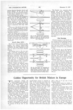
Many of these Firestone-type units were seen on passenger and goods vehicles exhibited at the 1957 Frankfurt Show and the accompanying diagrams show the front and rear tsuspension layouts of the German ,Bussing, Henschel, M.A.N. and Krupp vehicles. In the case of the Krupp, only the rear suspension is shown, as the vehicle exhibited was a tractor ifith conventional front springs.
‘. From these diagrams some of the many different ways in which the problem of axle location can be tackled are to be seen. The M.A.N. and Krupp rear suspension layouts are not dissimilar in general application. Only two bellows units per axle are employed, these being used in conjunction with large radius arms.
In the case of the M.A.N. layout these arms are arranged triangularly in plan view to give the necessary lateral location, in addition to absorbing driving and braking torque reactions.
With the Krupp layout, however, the radius arms'Ite beneath, and parallel to, the chassis frame members, and additional location and reaction are provided by a triangular frame above the axle, pivoted on the same vertical axis as the main radius arms.
M.A.N. Have I.F.S.
The M.A.N. front suspension is independent, and employs unequal-length wishbones, the air-spring bellows being mounted on the upper wishbone on each side, as shown in the front elevation drawing.
The Bussing layout at the rear comprises a beam-type arrangement with a bellows unit at each end, and location is given by a triangulated frame pivoted at the chassis centre line. There are four bellows units on the rear axle with this system and two are employed for the front suspension, a conventional beam axle being employed with a triangular frame for location, as at the rear.
M.A.N.. Krupp and Bussing employ Knorr levelling valves. 'All have two levelling valves at the rear axle, one on each side. The Bussing has a single frontsuspension levelling valve and the M.A.N., naturally enough, because of its independent front suspension, has a levelling valve adjacent to each front bellows. The Henschel rear suspension shows possibly the greatest originality of thought, because the axle location is catered for by the two light semi-elliptic springs. These do not appreciably affect the suspension characteristics, which are provided by four bellows units and font telescopic dampers. There is a Westinghouse levelling valve on each bellows.
Subject to there being little delay in the valve actuation, it is not inconceivable that the pressures inside these bellows can be instantaneously adjusted to provide inherent reaction to braking and driving torques. The scheme of the front suspension for the Henschel is broadly similar to that for the Bussing, and with both these layouts transverse Panhard rods are used to provide lateral location. Similar rods are also employed on the rear suspension of the M.A.N. and Bussing buses.
First Drawings
With the exception of the M.A.N. layout, all these German suspension systems were illustrated by photographs in The Commercial Motor on September 27, but this is the first occasion on which even schematic drawings have been published of them.
In the M.A.N. bus at the Frankfurt Show, the layout differed from the one shown in the drawing in that rolling-lobetype suspension units were employed, as opposed to bellows-type springs. Geometrically the layout appears to be similar, but the body of the bus exhibited made it difficult to ascertain the exact suspension design at the rear.
At the Turin Show in October there were no goods or passenger vehicles with any of these Saga units fitted, although another make of spring was seen on a Casaro coach.. It is known that Lancia are considering the use of the Saga Torpress units on a coach, the bellows employed being of 8.95-in, diameter, with a maximum static inflation pressure ol 100 p.s.i.