Buses Tracked by New Electronic System
Page 24

If you've noticed an error in this article please click here to report it so we can fix it.
A NEWLY developed system by means of which the positions of r-k individual buses can be made known to route controllers as the vehicles progress was demonstrated by the London Transport Executive last week. It has emerged from the experimental stage, and is initially to be applied to No. 74 service from Camden Town to Putney Heath. Later it may be used on 60 of the undertaking's routes most heavily affected by congestion.
The optical-electronic system has been devised by L.T.E. Electrical Testing Section, but may be offered for commercial production by a manufacturer with. the necessary capacity. In this case it will also be available to other operators. It is known as B.E.S.I., or the Bus Electronic Scanning Indicator.
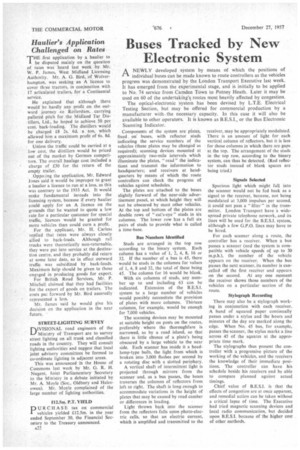
Components of the system are plates, fixed on" buses, with reflector studs indicating the service numbers of the vehicles (these plates may be changed as required); scanning devices mounted at approximately two-mile intervals which illuminate the plates, " read " the indications and transmit the information to headquarters; and receivers at headquarters by means of which the route controllers can check the progress of vehicles against schedules.
The plates are attached to the buses slightly forward of the near-side advertisement panel, at which height they will not be obscured by most other vehicles. At the top and bottom of the plates are double rows of "cat's-eye" studs in six columns. The lower row has a full six pairs of studs to provide what is called a time-base.
Bus Numbers Identified
Studs are arranged in the top row according to the binary system. Each column has a value of 1, 2, 4, 8, 16 or 32. If the number of a bus is 45, there would be studs in the columns for values of 1, 4, 8 and 32, the total of these being 45. The column for 16 would be blank.
With six columns of studs, any number up to and including 63 can he indicated. Extension of the B.E.S.I. system to a large number of vehicles would possibly necessitate the provision of plates with more columns. Thirteen columns, for example, would be enough for 7,000 vehicles.
The scanning devices may be mounted at suitable height on posts on the routes, preferably where the thoroughfare is narrowed, as by a road island, so that there is little chance of a plate's being obscured by a large vehicle to the near side. Each scanner has inside it a headlamp-type bulb, the light from which is broken into 3,000 flashes per second by a rotating disc with a slotted periphery.
A vertical shaft of intermittent light is projected through mirrors from the scanner and, as a bus passes, the beam traverses the columns of reflectors from left to right. The shaft is long enough to accommodate variations in the height of plates that may be caused by road camber or differences in loading.
Light thrown back into the scanner from the reflectors falls upon photo-electric cells, so that an electric current, which is amplified and transmitted to the
receiver, may be appropriately modulated. There is an amount of light for each vertical column of reflectors, but it is less for those columns in which there are gaps at the top. The arrangement of the studs in the top row, according to the binary system, can thus be detected. (Red reflector studs instead of blank spaces are being tried.) Signals Selected
Spurious light which might fall into the scanner would not be fed back as a signal to the receiver, because, not being modulated at 3,000 impulses per second. it could not pass a " filter " in the transmitter. London Transport have a widespread private telephone network, and its lines will be used for the B.E.S.I. system. although a few G.P.O. lines may have to be hired.
For each scanner along a route, the controller has a receiver. When a bus passes a scanner (and the system is compatible with vehicle speeds of up to 30 m.p.h.), the number of the vehicle appears on the receiver. When the bus passes the next scanner, its number is cancelled off the first receiver and appears on the second. At any one moment the receiver shows those numbers of the vehicles on a particular section of the route.
Stylograph Recording
There may also be a stylograph working in conjunction with each receiver. A band of squared paper continually passes under a stylus and the hours and minutes of the day are marked along the edge. When No, 45 bus, for example, passes the scanner, the stylus marks a line across 45 of the squares at the appropriate time mark.
The stylographs thus present the controller with a progressive picture of the working of the vehicles, and the receivers the knowledge of their immediate positions. The controller can have his schedule beside his receivers and be able to compare planned against actual timings.
Chief value of B.E.S.I. is that the effects of congestion are at once apparent, and remedial action can be taken without a critical lapse of time. The Executive had tried magnetic scanning devices and local radio communication, but decided upon B.E.S.I. because of the higher cost of other methods.


