


Back Axle with Hub Reduction Gear
Page 46
If you've noticed an error in this article please click here to report it so we can fix it.
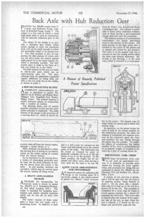
PATENT No. 580,894 comes from F. Cowell and Kirkstall Forge, Ltd., both of KirkstalI Forge, Leeds, 5. The subject is a live axle in which a small high-speed shaft is used in conjunction with an epicydic,reduction gear in the hub,
The object of the design is to provide a reduction gear which, whilst sturdy enough to carry the maximum load, will yet be small enough to allow the detachable wheel to be passed over it. The chief problem is that of supporting the idler pinions (1) which convey the drive from the central splined shaft pinion (2) tothe outer annulus (3), which is internally toothed. The lastnamed piece is made in the form of a hub cap bolted on to the wheel.
The idler pinions in this case are made in side-by-side pairs which run on roller-bearing pins (4). The pins, although long, are adequately supported against deflection by being held, not only at the two ends, but in the middle, as shown in point 5.
A REFUSE-COLLECTING OUTFIT
A COMPLETE refuse-collection sysr1 tern is described in patent No. 580,934, by D. Walker and Walker Bros. (Wigan), Ltd., Pagefield Iron Works, Wigan, Lancs. The scheme employs a master powered vehicle, in conjunction with a number of trailers.
The drawing shows one of several possible variations; in this case the semitrailer principle is employed. The chief feature of the patent is the provision of a moving floor (1), which is driven by a power take-off from the tractor engine, through a clutch shown at 2.
Other methods are described in which the moving floor is driven by an electric motor on the trailer, taking its current from the tractor battery.
As an alternative to the moving floor, a system of telescoping partitions may be used, but the basic principle of taking the power from the tractor is the
same. In still another variation, the secondary vehicle may be carried upon the tractor, instead of being towed.
A HEAVY LOW-LOADING TRAILER
ATRAILER for transporting the heaviest loads is shown in patent No. 580,879, by J. Donaldson-Hudson, 50, Pall Mall, London, S.W.1. The trailer is intended for handling locomotives and similar wheeled machines which can be run off on their own wheels.
The trailer consists of three main units—a front and rear bogie, and a connecting frame. In addition, at each idA
end is a bell crank (1), pivoted on the frame and bait-jointed on to the central point of the bogie. The bellcranks can be raised or lowered by pairs of hydraulic cylinders (2) so as to lift the frame or lay it on the ground. In the latter position, the bogies can be unpinned and taken away, thus leaving a clear path for the load to be run off.
AyNEW VALVE ARRANGEMENT FOR TWO-STROKES
AN improved means for admitting the charge to the working space of a two-stroke engine is the subject-matter of patent No. 580,631, which emanates
from R. Fisher, 47a, Kenilworth Road, Leamington Spa. The scheme is applicable to those using crankcase compression or those having a pre-compressed charge delivered into the crankcase.
The exhaust system is of conventional construction. tne piston uncovering ports at the bottom of the stroke. The main novelty is the inlet valve; this is located in the crown of the piston and is opened and closed by gas pressure. The valve is of the poppet type, but is unusual in that the seating moves whilst the male cone remains stationary. Referring to the drawing, I is the male cone, which is attached to a cross-mem ber in the piston. The female cone (2) slides inside the piston and is fitted with sealing rings.
In operation, on the power stroke the valve is held in the closed position by the combustion pressure, but when the exhaust is completed, the superior pressure in the crankcase opens the valve and transfers the new charge through the piston into the cylinder. To nullify the effects of acceleration, the sliding member of thc valve is counterbalanced by an annular weight (3) coupled to the valve by a pair of rocking levers (4).
PREVENTING TYFIE CREEP WITH large low-pressure tyres, such Vir as are used on agricultural tractors, it is desirable to provide some means for locking the cover against creep, and proposals for doing this are contained in patent No. 580,613 by the Firestone Tire and Rubber Co., Akron, Ohio, U.S.A.
A section of rim and tyre is shown, and it will be seen that the rim base is of tapering section, being thickest at point 1. On the other side, a detachable wall (2) is held on to the rim by a groove (3) in the rim. The assembly is completed by a loose ring (4) which is keyed against rotation by a dowel (5) engaging the valve-slot. The loose ring is tapered after the manner of the opposite side of the rim, so that, when the tyre is inflated, it is forced up the two slopes and powerfully grips the rim.