


New British Two-stroke Oil Engine
Page 33
If you've noticed an error in this article please click here to report it so we can fix it.
Using the Kadenacy Exhaust Scavenging System, the Foden Two-stroke Engine Affords a Comparatively High Power Output for Its Size and Weight. Tests Reveal High All-round Performance and Exceptional Fuel Consumption Figures.
APRELIMINARY announcement has been made by Fodens, Ltd., Sandbach, of its two-stroke highspeed oil engine, which is now being produced for use in commercial vehicles. The new engine has been aesigned on the two-stroke principle because of the high power output avail, able in proportion to the size and weight of the unit, an important feature which ultimately could be used to increase body space and payload capacity.
The six-cylindered unit, of 85 tom. bore. 120 mm. stroke, and 4,090 c.c. capacity, has an output of 126 b.h.p. at 2,000 r.p.m., its governed speed. From the manufacturer's tests, the road performance is high and a fuel consumption of 250 ton m.p.g. has been obtained. Its weight, less electrical equipment, is 1,100 lb.
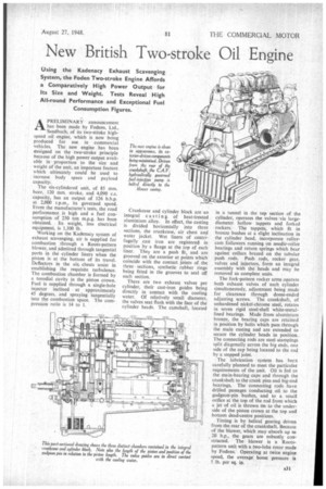
Working on the Kactenacy system of exhaust scavenging, air is supplied for combustion through a Roots-pattern blower, and admitted through tangential ports in the cylinder liners when the piston is at the bottom of its travel. Deflectors in the ain chests assist in establishing the requisite turbulence. The combustion chamber is formed by a torodial cavity in the piston crown. Fuel is supplied through a single-hole injector inclined at approximately 45 degrees, and spraying tangentially into the combustion space. The compression ratio is 14 to 1.
Crankcase and cylinder block are an integral casting of heat-treated aluminium alloy. In effect, the casting is divided horizontally into three sections, the crankcase, air chest and water jacket. Wet liners of centrifugally .cast iron are registered in position by a flange at the top of each liner. They are a push fit, and are grooved on the exterior at points which coincide with the contact joints of the three sections, synthetic rubber rings being fitted in the grooves to seal off each section.
There are two exhaust valves per cylinder, their cast-iron guides being directly in contact with the cooling water. Of relatively small diameter, the valves seat flush with the face of the cylinder heads. The camshaft, located in a tunnel in the top section of the cylinder, operates the valves via largediameter hollow tappets and forked rockers. The tappets, which fit in bronze bushes at a slight inclination in the cylinder head, incorporate rollercam followers running on needle-roller bearings and return springs which bear against collars brazed on the tubular push rods. Push rods, rocker gear, valves and injectors, form an integral assembly with the heads and may be removed as complete units.
The fork-pattern rocker arms operate both exhaust valves of each cylinder simultaneously, adjustment being made for clearance through dome-ended adjusting screws. The crankshaft, of unhardened nickel-chrome steel, rotates in seven rigid steel-shell white-metallined bearings. Made from aluminium bronze, the bearing caps are retained in position by bolts which pass through the main casting and are extended to secure the cylinder heads in position. The connecting rods are steel stampings split diagonally across the big ends, one side of the cap being located to the rod by a stepped joint.
The lubrication system has been carefully planned to meet the particular requirements of the unit. Oil is fed to the main-bearing caps and through the crankshaft to the crank pins and big-cod bearings. The connecting rods have drilled passages conducting oil to the gudgeon-pin bushes, and to a small orifice at the top of the rod from which a jet of oil is thrown on to the underside of the piston crown at the top and bottom dead-centre positions.
Timing is by helical. gearing driven from the rear of the crankshaft. Because of the blower, which may absorb up ka 20 h.p., the gears are robustly constructed. The blower is a Rootspattern unit with a two-lobe rotor made by Fodens. Operating at twice engine speed, the average boost pressure is 5.1b, per sq. in.