


Control of Self-levelling Valves
Page 76
If you've noticed an error in this article please click here to report it so we can fix it.
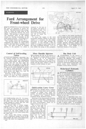
rONSTANT-HEIGHT pneumatic sus
pension systems are often provided with a delay device for disregarding small transient shocks. But if the vehicle corners, first left and then right, the delay device may permit it to take the second bend at a dangerous angle of tilt. These are the views expressed in patent No. 885,519 which proceeds to describe a system free from this defect. (Westinghouse Brake and Signal Co., Ltd., 82 York Way, London, N.1.) Referring to the diagram, pneumatic bellows (I) form the main -suspension units. Each bellows is controlled by its own height-sensing valve (2). In cornering, one side would be pressed down and the other rise, and the sensing valves would attempt to rectify this roll, with the results mentioned above. To prevent this, a master height. responsive valve (3) is placed in series with the other two. This valve is coupled to a mid-point on the axle, so that it is operated by the mean height of the vehicle and not by one wheel rising while
• the other falls.
This means that during cornering, unless a significant change occurs in the mean height, the centre valve temporarily renders the other two inoperative.
a18
More Durable Injectors
T0 prolong the life of an injector is the aim of a design shown in patent No. 885,627 by A. B. Gotawerken, Goteborg, Sweden. In this scheme, a bottom plug containing the seating of the needle and the spray orifices is made of tungsten carbide instead of steel.
Quick-action Lorry Cover
PATENT No. 885,082 shows a scheme in which a lorry sheet can be quickly extended or folded away when not needed. (D. Smith and Sohn Smith and Co. (London), Ltd., Hainault Works, Chadwell Heath, Romford, Essex.)
Referring to the diagrammatic drawing, the cover is carried upon a linkage (1) of the lazy-tongs type. Vertical extensions (2) carry cross-members which act as support hoops for the cover.
Two or more legs (3) descend to the edge of the body; these arc fitted with rollers that run along a track on the side. A fixed upright (4) is also provided at the rear. The sheet can be rapidly folded up against the back of the driver's cab (5).
Bus Body Unit
PAA STANCHION for the interior of passenger service vehicles is shown in patent No. 886,568. The upright is held both at top and bottom in a rubber mounting so as to reduce any stresses caused by deformation of the body. The patent comes from Metalastik, Ltd., Evington Valley Road, Leicester.
Resin-faced Hydraulic Cylinders
AMETHOD of manufacturing hydraulic -or pneumatic cylinders to high dimensional accuracy is shown in patent No. 884,531. The scheme proposed is to 'line a rough-cast cylinder with a smooth surface of epoxy resin. Web Schelepperwerk Nordhausen, 30e Freiherr-vorn-Stein Strasse, Nordhausen, Harz, Germany.) The drawing shows the method used. A rolled or cast body (1) has poured into it a measured quantity of epoxy resin (2). A highly finished core-piece (3) is then inserted and displaces the resin up the cylinder to form a liner.. Concentricity is ensured by the provision of a centre
point (4) at the bottom and a sleeve (not shown) at the top.
Setting time is dependent upon tern
• perature and can be anything between 10 hours and 4 minutes. Sticking of the core to the resin'is prevented by coating it with a release agent. A pre-finished liner can be fitted in a similar manner.