


Preventing Reversal of Oil Engines
Page 92
If you've noticed an error in this article please click here to report it so we can fix it.
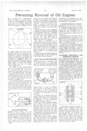
IT is possible for a compression' ignition engine, in certain circumstances, to run backwards by drawing in air from the exhaust system and exhausting via the intake manifold. When this happens, it is difficult to stop the engine because the usual suctionoperated governor is then under compression, and sets the pump into the full-delivery position; meanwhile the engine is completely out of control and is racing at a dangerous speed. To eliminate the possibility of this occurring is the aim of a modified injection pump shOwn in patent No. 742,583 (Ford Motor Co., Ltd., 88 Regent Street, London, W.1).
The shape of the injection-pump cams are so altered that in the event of a reversal of drive, the fuel is injected at a non-effective point in the cycle. The drawing shows, in full line, a standard form of cam. Normally, injection starts at point 1 and the cam, if run backwards, would, by virtue of its symmetry, inject at about the same moment as indicated by 2.
The invention consists of lengthening the peak of the earn to extend over the angle shown by the chain line (3). In reverse, injection would not then occur until point 4 was reached which represents a moment when any fuel injected would be blown away by the departing air.
EQUALIZED BRAKING
FROM Jensen Motors, Ltd., 124Chancery Lane, London, W.C.2, comes patent No. 742,943, which deals with the control of the proportion of braking applied to the front and rear wheels. As is well known, whilst the front wheels may be more heavily braked than the rear ones, the conse
B34 quences Of a front-wheel skid could be so serious that designers are naturally cautious of giving the front wheels their full share. The scheme shown in the patent is arranged to give the front wheels an increasing share of the work as the force applied to the brake pedal increases.
The drawing shows the arrangement as applied to hydraulic brakes, although it is not limited to this type. The pedal' works both the master-cylinder (1) for the front brakes and another (2) for the rear ones. The pedal force is applied to the middle of a link (3), which connects the two pistons.
The thrust is transmitted via a sloping slot (4) and it is easy to appreciate that an increased pull tends to roll the rod end towards the upper end of the slot against the force of a spring (5). The result is that the rod applies a greater proportion of its pull to the upper cylinder as the applied, force increases.
If the pedal be only lightly depressed, the spring tension is not so much and a more equal division is made.
A NEW TYPE OF INDUCTION PIPE THE provision of a hot-spot in an I induction pipe is a well-known means for assisting vaporization of the fuel, but the heat also thins out the ingoing mixture so that the cylinders do not receive a full charge. On the other hand, if no heat is supplied to -the induction system, a heavier charge is formed, but vaporization may be imperfect.
A scheme for satisfying these conflicting requirements forms the subject of patent No. 741,605 (L. Grillet and H Regnauh, 175 rue d'Aguesseau, Boulogne-sur-Seine, France).
The layout of the proposed induction pipe is shown in the drawing. In line with the choke tube is an exhaustheated hot-spot (not shown) and the vaporized mixture passes from this along the pipe in the normal way, The novelty consists of the use of a pair of inner pipes (I) which are taken from the choke-tube and extend into space '2
adjacent to the inlet valves. • The mixture that is drawn through the valves is cold, but is, nevertheless, fully vaporized due to the high flow velocity through the small pipes and their nozzles (3). Valves (4) are pro
vided and it is claimed that by their use the temperature of the charge can be adjusted to the optimum.
A LIGHTWEIGHT OIL ENGINE
DATENT No. 742,719 (A. Sanders, Redinnick House, Penzance) refers to a design of lightweight oil engine suitable for cars and light vans. A compression ratio of from 10 to 1 to • 14 to 1 is quoted for a cylinder bore of 2# to 3 in.
With such a low ratio there may be some slight difficulty in starting, not so much under normal temperature conditions as under conditions of extreme cold. The subject of the patent is a device to facilitate starting.
It works on well-known principles, injecting a spray of ether-fuel mixture at the moanent of starting. To ensure correct timing, the starter switch is arranged so as to be operated by the pressure generated by the hand-worked injector.
AUTOMATIC ADJUSTMENT FOR HYDRAULIC BRAKES A CONSTANT-CLEARANCE ad justment for the expanders of a hydraulic braking system is dealt with in patent No. 742,395 (J. Belenkij, 4 Arasska, Praha XIX, Czechoslovakia).
The cylinder contains the two main pistons (1) and between them a pair of auxdiary ones (2). These are cut away at three points so that they inter-engage after the manner of a dog-clutch, and a circumferential groove (3) is cut round the assembly. A stop-ring (4) limits their movement to that permitted by the groove clearance. Between each auxiliary piston and its main one is a one-way cup-washer (5).
In operation, hydraulic pressure is applied at the mid-point and all the pistons move outwards until the auxiliary ones are arrested by the ring. If more movement he necessary, the main pistons then go on alone, the fluid passing through bores 6 and forcing its way past the cup-washers. On the return stroke, the stop-ring controls the movement, and any fluid remaining behind the cup-washers stays there as a take-up of slack.