


Ball-bearing Thread Steering Box
Page 48
If you've noticed an error in this article please click here to report it so we can fix it.
A Resume of Patent Specifications that Have Recently Been Published
DOUBLE-DUTY INTERIOR HEATER
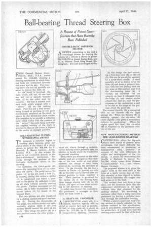
ADEVICE comprising a fan and a centrifugal blower for heating the interior of a vehicle is shown in patent No. 518,379 by Joseph Lucas, Ltd., and E. A. Watson, Great King Street, Birmingham. The unit is arranged so that FROM General Motors Corp., Detroit, Mich., U.S.A., comes patent No. 518,405, showing a steering mechanism in which bearing balls are interposed between the screw and its nut, The drawing shows the nut (4) partially cut away to expose the balls (2).
As the screw is revolved, the balls which roll out of one end are led via a smooth transfer tube (1) to the other end for re-entry. The nut is formed with rack teeth which engage with a " sector " (3) on the rocking shaft. Part 3 is not a true sector, being formed as portions of two gears eccentrically mounted on the shaft, as shown by the dOtted-line pitch circles. The intention is to provide a reduction ratio which varies with the position of the " sector," the ratio being such that the angular velocity of the shaft in relation to, that of the screw is highest in the centre or straight position.
SELF-ADJUSTING CLUTCH. WITHDRAWALDEVICE
'T'Omaintain a constant degree of slack between pedal and clutch-plates is the object of a device shown in patent No. $18,300, by F. Heacock, 7, Manor Gardens, Acton, London, W.3. In this scheme the pedal is not connected directly to the clutch-withdrawal mechanism, but works through the medium of the hydraulic mechanism shown in the drawing.
In operation, the clutch-pedal (3) moves the operating lever (7) to withdraw the clutch. The pedal moves the piston (4) to the left until a leak (1) is covered; during this action a spring (5) is compressed and exerts a pressure on the piston (6) sufficient to take up all slack without actually moving the plates: Further movement of the piston (4) is fully transmitted to the second piston (6) by means of the trapped fluid.
The two pistons are alsO connected by a sliding ratchet-and-pawl mechanism (2). During the downstroke of the pedal, the ratchet device can automatically shorten itself if the lost motion should exceed the pitch of the teeth. This brings the piston (6) to a new position nearer the other piston. warm air, drawn through a radiator, can be directed either generally into the interior, or locally about the windscreen to prevent steaming.
Both rotors are mounted on the same spindle, and are arranged so that only one of the two works at any given moment, the change of duty being achieved by reversing the direction of drive. In the drawing, the fan has a number of blades (4) pivoted on rods (3) so that they can be moved from the normal position to form, together, a disc. Their position is governed by the spokes (5) of the driving boss; these engage sloping tails (6) on the blades, and open or close them according to the direction of running.
A radial-vane blower (1), concentrically positioned, is arranged to blow warm air from outlet 2.
A HEAVY-OIL VAPORIZER
ACARBURETTER which will, it is elaimed, function equally well on petrol or heavier fuel such as paraffin, oil fuel, or even crude oil, is shown in patent No. 517,385, by E. Danielsen,
Onsgaardsvej, Hellerup, Denmark. In this design the fuel arrives, via a two-way cock (6), at the jet (7); this can be pre-set for aperture by a screw-down needle. A small quantity of air is drawn in by the holes (5) and forms a primary mixture with the fuel issuing from the jet; some of this mixture may feed the slow-running tubes (8). A venturi (2) increases the air velocity so that it rebounds from the bulge (1) and creates eddies around the fuel jet, and the performance of the carburetter is said to be due to the shape of the passage about the point (1).
The normal throttle (9) is connected with an air throttle (4) via light springs (a). When the throttle (9) is suddenly opened, the air-valve (4) closes slightly ; this gives a momentary richness for accelerating. When the engine speed has risen, the air-valve (4) is reopened by the increased velocity of the air.
NEW MANUFACTURING METHOD FOR LEAD-BRONZE BEARINGS
COPPER-LEAD alloys for big-ends A.--,have been found to possess many advantages, but much difficulty has been encountered in producing an homogeneous alloy, probably on account of the wide differences in weight and melting-point of the two metals. A means for overcoming this trouble is disclosed in patent No. 518,206, which comes from Heraeus Vacuurnschmelze A.G., and others, Hanau, Germany.
The proposed scheme is to place the copper alone in the steel shell in the form of a finely woven mat of wire; this assembly is then dipped in molten lead which infiltrates the copper mat and unites it to the shell.
This method does not form a true alloy, but the inventors claim that the copper-lead distribution is far niore uniform than that obtained by the melting method. No machining is necessary other than a sizing operation performed by forcing a polished mandrel through the assembled bearing.
Whilst a mixed copper and lead bearing surface is clearly afforded by the scheme outlined in this specification, and its anti-friction characteristics may be satisfactory, it would seem that the melting point would be that of the lead.