


Patents Completed.
Page 22
If you've noticed an error in this article please click here to report it so we can fix it.
MOTOR TRACTOR—Saunderson.— No. 28,754i1909, dated 8th July, 1910.— This invention relates to motor tractors which are available for ploughing, haul lug and other agricultural purposes, and the object of the invention is to provide an arrangement for enabling the belt pulley for driving threshing and other machines to be disconnected from the propelling mechanism. In the form illustrated the engine shaft lies across the vehicle, and is provided with a flywheel at one end. This flywheel forms one member of a cone clutch, the other member of which is fast on a sleeve on the same shaft. On this sleeve is fixed a pinion which engages with a spur wheel, which, through the gearbox, drives the transmission gear. This pillion is slidably mounted on the sleeve with a key on the outer end, and fast on the sleeve is a belt pulley. The pinion is arranged to be drawn inside the pulley when it is required to disconnect the driving mechanism. It will thus be seen that the, clutch permits the entire disengagement of the engine from the transmission gear or the belt pulley, and the extra movement of the pinion allows the transmission gear to be thrown out of action.
MOTOR VANS.—Buck.—No. 18,223, dated 2nd August, 1910.—In this specification is described an arrangement whereby the load of motor vans carrying light but bulky goods is better distributed between the front and back wheels. In the case of furniture vans. for example, an upper front portion of the body of the van is constructed ex. tending over the engine, and forming a recess in which the engine is placed, and in which there is room for the driver. Goods can be packed into this space, thus ensuring that a portion of the load is carried on the front wheels and the whole of it not entirely carried upon the wheels of the back axle.
AGRIC.ULTITRAL MOTOR.—Woods. —No. 11,244. dated 6th May, 1910.—The principal feature in connection with this machine is the arrangement of gearing for transmitting the drive. The twospeed clutch is illustrated in plan and elevation, and is constructed in the following manner. Two inner members of cone clutches are respectively fast on and slidably mounted on the engine shaft ,i the end of which latter is shown at the righthand side of the drawings. Sleeves mounted on this shaft carry the outer members of the clutches as well as a suitably-sized gear wheel to give two speeds. On the end of the sleeve is mounted a bevel pinion, which meshes with and drives two crown bevels in opposite directions. These are mounted loosely on a transverse shaft from which the road wheels are driven, and the drive is transmitted when desired through either one
by a suitable dog clutch. When a reaping or mowing attachment is used, it is driven by suitable gearing from the motor, for example, by belt or chain, and the driving mechanism will at the same time be left. in action. Other details are described which permit the machine to be used as a threshing machine, winnowing machine or the like,
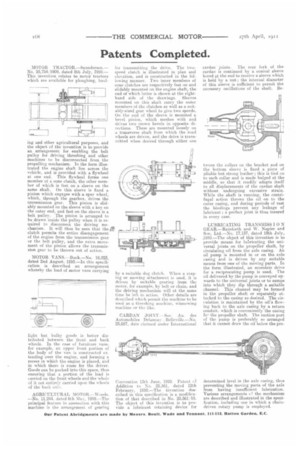
CARDAN Sue. An. des Automobiles Delauney
25,687, date eiaimed under International Convention 13th June, 1910. Patent r.f Addition to No. 25,561, dated 12th February, 1910.—The invention described in this specification is a modification of that described in No. 25,561110. The object of this invention is to provide a lubricant retaining device for newton. joints. The rear fork of the cardan is continued by a conical sleeve bored at the end to receive a sleeve which is held by a nut; the internal diameter of this sleeve is sufficient to permit the necessary oscillations of the shaft. Be
tween the collars on the bracket and on the bottom sleeve is fixed a piece of pliable but strong leather ; this is tied on to each collar and is made bulged at the middle, so that it readily adapts itself to all displacements of the eardan shaft without undergoing excessive strain. While the shaft is running, the centrifugal action throws the oil on to the outer casing, and during periods of rest the bindings prevent any leakage of lubricant ; a perfect joint is thus insured in every case.
LUBRICATING TRANSMISS 10 N GEAR.—Rainforth and W. Napier and Son, Ltd.—No. 17,137. dated 19th July, .1910.—The object of this invention is to provide means for lubricating the universal joints on the propeller shaft, by circulating oil from the axle easing. An oil pump is mounted in or on the axle casing and is driven by any suitable means from one of the moving parts. In the form illustrated, an eccentric drive for a reciprocating pump is used. The oil delivered by the pump is conveyed upwards to the universal joints or to sumps. into which they dip through a suitable channel. This channel may he formed in the propeller shaft or separately attached to the easing as desired. The circulation is maintained by the oil's flowMg back to the axle casing by a return conduit, which is conveniently the casing Ice. the propeller shaft. The suction port of the pump is preferably so arranged that it cannot draw the oil below the pre
determined level in the axle casing, thus preventing the moving parts of the axle from having insufficient lubrication. Various arrangements cr the mechanism are described and illustrated in the specification, including one in which a chaindriven rotary pump is employed.