


Piston with a Semi-rotary Motion
Page 56
If you've noticed an error in this article please click here to report it so we can fix it.
A Resume of Recently Published Patent Specifications
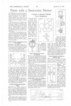
INTENDED for two-stroke oil engines, j. a novel type. of piston is Shown in patent No. 587,777, by W. Howald, Zurich, Switzerland. The piston is rotated through a small angle on every stroke, so that it can be used to control cylinder ports, inthe manner of a sleeve valve.
The connecting ,rod is attached to the piston at two points, one being a balland-socket seating (1) to withstand the power thrust, whilst the other is a pivot pin (2), which produces the rotary motion. The pivot pin is a tight fit in the connecting rod, but is retained in a housing(3) located in one side of the
piston skirt, • The problem of assembling the ballseating is overcome by making it elliptical, as at (4), so that it can be inserted through an elliptical bore (5) and then given a quarter-turn to secure it. Although-its angular rotation is also in this plane, it does not travel far enough to risk unlocking. • FRONT-WHEEL SUSPENSION FOR ELECTRICS
DATENT No. 588,821, from A. E. I and A. C. Morrison, 52, Woodhouse Road, Quorn, Leics, describes a method of independently suspending the front wheels of a battery-electric vehicle. The drawing shows a plan view of the proposed arrangement, in which two
electric motors (1) are each geared to a single road wheel, and can be swivelled about ball-jointed pins (2) for steering. . The springing is based on a parallelogram linkage, -ccinsisting of upper members (3) and lower. members (4), both sets being pivoted on the main cross-member by pins (5). The upper links are also used to contain the quarter-elliptic , springs.
As the cross-member carries the,steering gear control pedals (6) and the driving motors, it can be quickly detached and exchanged for a replacement unit when repairs become necessary.
MAKING PISTON RINGS FROM ' WIRE
PATENTNo. 588,337,_ entered by R. C Cross and Cross Manufacturing Co, Ltd., of Bath, Somerset, out lines a scheme for ma:nufactairing piston rings by winding red-hot wire around a mandrel. In the p‘ast, a specially formed wire has been found necessary, but the present process can use standard round wire.
The patent shows various types of machine used in the manufacture of the rings. The wire (1) is heated and fed to a formed groove (2) in a mandrel,
and is then forged. o shape by a roller (3), which forces it into close contact with the groove. Additional rollers (4) confine the ring to a circular form as the operation proceeds.
The wire may be pre-cut to ftie correct length, if single rings be • required, or it may be coiled like a spring and' then cu t lengthwise.
The forging operation spay also be used to heat-treat the rings by providing quenching jets at suitable points.
TOOL FOR TRUING VALVE SEATINGS
'fore-cut the wearing surface on valve I ,seats is the purpose of -a tool shown in patent No.588,943, by P. Hollinshead, "Avondale," Station Road, North Hykeham, Lincs.. The tool is similar in action. to a carpenter's smoothing plane, Cutting a smooth surface free from chattermarks, The .tool is shaped like a valve, being provided with a stem to fit the guide and a conical head which is preferably hardened. A cutting tool (1) is located in an -angular hole, and:can-be fed into action by an 'adjusting screw (2). 'The' support. affordedby' the coned -seating. . ensures freedom from chatter,, a defect sometimes found in cutters supported only. by the stem. The head may be fitted with a tommy-bar for hand use or a shank suitable for machine .drive.
INCREASING GROUND ADHESION 'OF TRACTORS •
ASCHEME for improving the traction. of an agricultural' tractor is shown ip.patent No. 57,454,f rem L. Dufour; QeneVa., Switzerland,ty adding part of the trailer load,.to the, driving wheels, they 'can be loaded to more than the
total weight of the tractor. . From the drawing it will be seen that the • engine and transmission unit is pivoted on the chassis, so that when coupled to a trailer it can assume an angle, as illustrated. The steering gear and the driver's seat are mounted on a bridge piece, which, being attached to the chassis, does not move.
It is claimed that, when travelling, inequalities of the ground cause only a slight variation of load on the driving wheels, because the pivoted part can vary its angle and maintain an approximately constant downward force.
LONG-WEARING CUTTER ON BQRING BAR
rro increase the durability of boring
' bar tools is the object of a scheme shown in patent N. 589,514, by A. Boswell and Morris Commercial Cars, Ltd., both of Adderley Park, Birmingham, 8.
The .drawing shows _the bar and cutter at work 'inside a bore. The cutter (1), is made in the form of a disc, so that it can' be rotated into a new position when one spot has worn. It can also be -adjuSted for depth' of cut by means of a screwhead (2); this turns an eccentric pin upon which the Cutter is centred. The cutter is finally locke.d in position by means ofa pail of screws on the side opposite to the .view ,.shown.