


Patents Completed.
Page 22
If you've noticed an error in this article please click here to report it so we can fix it.
• Complete specifications of the following patents will be sent to any address in the.United Kingdom by the Sale Branch, Patent Office, Holborn, upon receipt of eightpence per copy.
A Safe Starting Handle.
G. J. DaIlison.—No. 21,494, dated 29th September, 1911.—A pinion is mounted on the end of the crankshaft by means of a sleeve and set-screws, and the sleeve also carries loose on it a casing which covers the pinion and on this easing the handle itself is pivoted. Another lever is also attached to the cuing and this is pivoted and has a few teeth at its upper end engaging with the pinion, and further it has at its lower end a knob which can enter a recess in the handle. When the handle is cleae of the second lever, the rotation of th6 crankshaft merely turns a second lever until its teeth are out of engagement with the pinion. This frees the whole system. When the handle is pushed back and the knob on the second lever enters the recess in the handle, the whole system is fixed, and the engine may be turned by it. In the event of a backfire, the handle is pulled forward into its disengaged position.
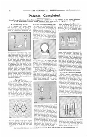
A Spring Shackle.
F. G. Garrett, No. 5133 of 1912, dated 29th February, 1912. Cognate Appli cation No. 15,976, dated 8th ,Tnly, 1912. —This specification describes a sprineehackle which comprises two heads with the usual eves for connecting them as re• .quirecl, anA having also formed on them collars by which a helical spring is engaged. It will be seen that the head.. are quite free to rotate with respect to one another, and to move apart under
the control of the spring. Preferably the main spring is of square section material and, if it be desired, an auxiliary helical spring may be used inside the main spring to couple the two heads together.
A Double-sided Detachable Rim.
W. Reid, No. 19,708, dated 5th September, 1911.—This specification describes a wheel rim where an ordinary hp is used on one side to engage the beading, and the other lip is dropped so that its diameter is about the same as the inner diameter of the tire. A recees is provided beside this rim. The detachable segments, which are used to grip the tire, a re held in this recess and bear against the lip of the rim_ It is stated that the segments are held in place by the angle at which they engage the lip of the rim, and also by the fact that they are circular. If 'desired this detachable rim may hi need on both sides of a wheel.
Rocking-lever Starting Gear.
E. W. Coleman and E. Rawlings, No. 24,508, dated 4th November, 1911.— This specification describes a starting gear which is arranged to provide for starting the engine from the driver's seat. The starting handle is coupled to a bevel wheel which meshes with two similar wheels mounted on a shaft. These two wheels are each provided with a clutch device so that they can drive the shaft in one direction. As the starting handle is moved to and fro, a drive is trans. mitted to the shaft through the two wheels alternately. The other end of the shaft carries loosely mounted on it a chain wheel geared to the engine crankshaft., and arranged to be driven by a plate clutch, on which the inner plate is fixed on the driving shaft, and the outer is pressed inwards by a spring to grip the chain wheel between the two plates. If it be desired, the chain wheel on the engine shaft may be provided with a free-wheel clutch device so that nit trouble can arise from hack-firing. Like an Expanding Book-case.
W. J. Gold, F. W. Beaching, and K3moch, Ltd.No. 28,776, dated 21st December, 1911.—This invention relates to a method of constructing engine frames which permits of the easy multiplication of cylinders. The frames are constructed of members of II-section and comprise, in the case of the horizontal engine illustrated, two L-shaped pieces which are coupled together at the righthand end by bolts passing through the short arms of the I.. and at the left-hand end carry the cylinder which is securely bolted to each member. If it be desired to make a two-cylinder engine, one of the L-members is exchanged for a similar T-shaped member which co-operates with an L-shaped member on each side of it to form the frames for two cylinders.
Dependent Lubricating Pumps.
Daimler Motoren Gesellschaft, No. 18,886 of 1911, dated under International Convention, 15th July, 1911. Patent of Addition to No. 18,618 of 1911.—This invention relates to the systems of lubrication where each pump acts as the dis tributing valve for another pump. It has hitherto been necessary to use one pump more than the number of parts to be lubricated, but this is now avoided and only the same number of pumps are used. They are of the differential piston type, the power stroke being made in the small cylinder. Oil is drawn from the reservoir into the annular chamber for each large piston, and is discharged
thence to the space under the small piston of the next pump. It is necessary to set the cranks so that the larger pistons cannot suck back the oil from another pump on its power stroke.