


Patents Completed.
Page 18
If you've noticed an error in this article please click here to report it so we can fix it.
Staggered Gearwheel Teeth. Cary Self-lubricating Leaf-springs. Combined Fan and Pump Arrangement. Governing the Fuel Inlet.
J. C. W. LLOYD AND THE S.M. CAR SYNDICATE, LTD.„ No. 23,364 dated 16th October, 1913.—This specification describes a simple construction of mechanism whereby only a single drive by belt, chain or gear is required for the radiator fan and for a pump for the circulating water.
The pump or impeller is mounted in the inlet pipe to the water-jacket at the front of the engine on the same support as the fan spindle. The fan has a hollow spindle and is mounted directly upon the support which is also hollow. The driving-shaft for the water pump extends through the support and is connected by a dog-clutch to the fan. The drive is applied to the fan spindle by a belt or otherwise, and any lateral pull duo to the belt is taken by the support and none of it transmitted to the water-pump spindle.
The support for the fan spindle may be mounted eccentri cally to provide for adjustment of the belt or chain.
S. E. PAGE (R. CouaxicE and C. H. TAYLOR), No. 3213/1914, dated 8th September, 1913.—In the governor described in this specification the fuel valve is opened to a variable degree for each working stroke of the engine. A cam mounted direct on the crankshaft is provided with a projection or nib and immediately behind it is a recess.
A pendulum-rod is held against the cam by a light spring ; when the engine is running at its normal speed this spring is sufficient to hold the roller continuously in contact with the cam. When the roller descends into a recess behind the projection the movement of the pendulum-rod opens the fuel valve. If the engine speed be excessive, however, the spring is not sufficiently strong to pull the pendulum-rod into the recess in the short time allowed; consequently the pendulum does not make a full stroke, as it is stopped on the further side of the recess. This means that the fuel-valve is open to a lesser extent than before, and the engine speed is consequently reduced.
The device may be connected to both the air and fuelinlets so that it is operative on both of them. A. E. TER.RY, No. 20,696, dated 13th September, 1913.— The gearwheel described in this specification is built up of a aeries of plates, and the teeth on the various plates are arranged staggered. The teeth on one plate are placed opposite the spaces between the teeth on an adjacent plate. In order to reduce the friction on the lateral faces of the teeth when in mesh with another wheel, spacing discs are inserted between each of the toothed discs. With this arrangement the teeth on another gearwheel can enter the spaces allotted in the first wheel without rubbing the sides of the teeth. The spacing plates are preferably of a diameter slightly less than that at the base of the teeth.
All the toothed discs and spacing plates are assembled on a hub which has an integral flange on one side and a separate flange on the other; the flanges are secured by bolts. These bolts lie partly in the laminations and partly in the hub so as to serve as keys between the discs and the hub.
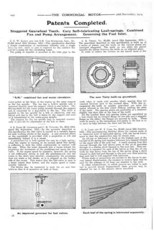
C. E. CARY AND W. T. CASE, No. 23,621 dated 18th October, 1913.—The accompanying drawing shows the various parts of an improved form of laminated spring, with the leaves drawn apart so that the construction may be clearly seen. An oil-cup or lubricator is fixed at the highest part of the top leaf of the spring and supplies lubricant to a channel formed on the upper side of the next leaf. A small opening from this channel through the leaf allows some of the oil to percolate through to a similar short channel in the next leaf. This construction is repeated for each of the leaves so that the oil can• work its way down from the top of the spring along a short channel in each leaf and through to the next one, thus ensuring that each leaf is well supplied with lubricant.
Where studs or projections are formed on the leaves to prevent lateral displacement, the recesses to receive them may be used for the passage of oil from one member to the next. In other constructions, in which grooves are rolled in each leaf to prevent lateral displacement, these grooves may be adapted for use in the manner above described.