


A Pneumatic Transmission System.
Page 2
Page 3
Page 4
If you've noticed an error in this article please click here to report it so we can fix it.
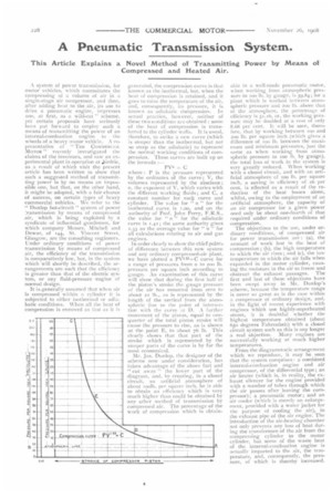
This Article Explains a Novel Method of Transmitting Power by Means of Compressed and Heated Air.
A system of power transmission, for motor vehicles, which necessitates the compressing of a volume of air in a single-stage air compressor, and then, after adding heat to the air, its use to drive a pneumatic engine, impresses one, at first, as a wild-cat " scheme, yet certain proposals have seriously been put forward to employ such a means of transmitting the power of an internal-combustion engine to the wheels of a heavy motor vehicle. A representative of " TRH COMNIERC I Al MOTOR " recently investigated the claims of the inventors, and saw an experimental plant in operation at i\irdrie, as a result of which visit the present article has been written to show that such a suggested method of transmitting power is by no means an impossible one, but that, on the other hand, it might be adopted, with a fair chance of success, on certain types of heavy commercial vehicles. We refer to the " Dunlop hot-circuit " system of power :ransmission by means of compressed air, which is being exploited by a syndicate of influential gentlemen, for which company Messrs_ Mitchell and Dewar, of t4.4., St. Vincent Street, Glasgow, are the consulting engineers. Under ordinary conditions of power transmission by means of compressed air, the efficiency of the transmission is comparatively low, but, in the system which will shortly be described, the arrangements are such that the efficiency is greater than that of the electric system, or any fluid-pressure engine of normal design.
It is generally assumed that when air is compressed within a cylinder it is subjected to either isothermal or adiabatic conditions. When all the heat of compression is removed as fast as it is generated, the compression curve is that known as the isothermal, but, when the heat of compression is retained, and it goes to raise the temperature of the air, and, consequently, its pressure, it is known as adiabatic compression. In actual practice, however, neither of these two conditions are obtained ; some of the heat of compression is transferred to the cylinder walls. It is usual, therefore, to strike a new curve (which is steeper than the isothermal, but not so steep as the adiabatic) to represent the normal working conditions of compression. These curves are built up on the formula :— PV=C
where : P is the pressure represented by the ordinates of the curve; V, the volumes represented by the abscissa; n, the exponent of V, which varies with the different working fluids; and C, a constant number for eactt curve and cylinder. The value for "n " for the isothermal curve is T.00, and on the authority of Prof. John Perry, F.R.S., the value for " n " for the adiabatic curve is 141; the same authority gives 5.33 as the average value for " n for all calculations relating to air and gas engines.
In order clearly to show the chief points of difference between this new system and any ordinary compressed-air plant, we have plotted a PVL33=C curve for a range of pressures from o to 200 lb. pressure per square inch according to gauge. An examination of this curve will show that during the first half of the piston's stroke the gauge pressure of the air has mounted from zero to about 22 lb., as is represented by the length of the vertical from the atmospheric line to the point of intersection with the curve it D. A further movement of the piston, equal to onequarter of the total piston stroke will cause the pressure to rise, as is shown at the point E, to about 76 lb. This clearly shows that that part of the stroke which is represented by the steeper parts of the curve is by far the most economical.
Mr. Jas. Dunlop, the designer of the scheme now under consideration, has taken advantage of the above fact and " cut away " the lower part of the diagram, and, by creating, in a closed circuit, an artificial atmosphere of about roolb, per square inch, he is able to obtain an efficiency which is very much higher than could be obtained by any other method of transmission by compressed air. The percentage of the work of compression which is obtain
able in a well-made pneumatic motor, m hen working from atmospheric pressure to loo lb. by gauge, is 59.84; for a plant which is worked between aunospheric pressure and 200 lb. above that of the atmosphere, the percentage of efficiency is 51.16, or, the working pressure may be doubled at a cost of only 8.68 per cent. It will be seen, therefore, that by working between ion and 200 lb. per square inch (which gives a difference of loci lb. between the maximum and minimum pressures, just the same as when working from atmospheric pressure to too lb. by gauge), the total loss of work in the system is very greatly reduced. When working with a closed circuit, and with an artificial atmosphere of too lb. per square inch, a saving in efficiency of 26 per cent. is effected as a result of the reduction of the heat losses alone, whilst, owing to the employment of an artificial atmosphere, the capacity of an air compressor for a given power need only be about one-fourth of that required under ordinary conditions of compression. The objections to the use, under ordinary conditions, of compressed air for power transmission are : (a), the amount of work lost in the heat of compression; (b), the high temperature to which the air rises; and (c), the low temperature to which the air falls when expanded in the motor cylinder, causing the moisture in the air to freeze and obstruct the exhaust passages. The first and last of these objections have been swept away in Mr. Dunlop's scheme, because the temperature range is never so great as is the case within a compressor of ordinary design, and, in the light of recent experience with engines which use highly-superheated steam, it is doubtful whether the highest temperature obtained (about 65o degrees Fahrenheit) with a closed circuit system such as this is any longer a real objection. Many engines are successfully working at much higher temperatures.
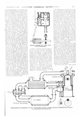
From the diagrammatic arrangement which we reproduce, it may be seen that the system comprises : a combined internal-combustion angine and air compressor, of the differential type; an air heater (which is, in reality, the ex
haust silencer for the engine provided with a number of tubes through which
the air passes after leaving the com
pressor); a pneumatic motor; and an air cooler (which is merely an enlarge inent, provided with a water jacket for the purpose of cooling the air), in the exhaust pipe of the air engine. The introduction of the air-heating chamber not only prevents any loss of heat during the transference of the air from the compressing cylinder to the motor cylinder, but some of the waste heat of the internal-combustion engine is actually imparted to the air, the temperature, and, consequently, the pressure, of which is thereby increased. With this added heat, it is possible that, under certain conditions of load, an efficiency of transmission of too per cent. may be obtained. As carried out in practice, the combined internal-combustion engine and air compressor is run at a constant speed, and is controlled by a governor, so that the supply of fuel may be regulated to give the highest thermal efficiency which can possibly be obtained with such a motor.
The air compressor is fitted with a piston type of inlet valve, but the outlet valve is of the automatic type. The valve gear consists simply of an eccentric that is fixed on a valve shaft, and the angular position of this eccentric vtelatively to the throw of the engine crankshaft may he altered through a range of 18ct degrees. This is effected by means of skew gears of different widths, as shown in the diagram ; as the narrow wheel is moved in an end wise direction, it is also, by reason of its being in mesh with the wider wheel, given a rotary motion. When the eccen tric is set at go degrees behind the throw of the crank, the compressor piston draws in a full-stroke volume of air for compression. When the eccen tric is 90 degrees in advance of the crank, the compressor does not com press any air and, consequently, will do no useful work. By altering the relative angular positions of the eccentric and the crankshaft, any volume of air from full-stroke volume to zero may be admitted to the compressor cylinder, and it is in this manner that the power and speed of the air engine is regulated to meet the needs of traffic conditions.
Throughout all the range of the eccen tric's positions, the engine will continue to run at a constant speed, and the full engine power will be absorbed either in compressing a small quantity of air to a high pressure, or a large quantity af air to a lower pressure. In other words, this plant is operated on the same principle as the constant-Watt output dynamos which form a part of many petrol-electric systems. By adoption of this principle, the pneumatic system of transmission is given the same high accelerating qualities as a series-wound electric motor.
Another peculiarity of this system is that the air is not worked expansively, but is admitted into the air-engine cylinder throughout the whole length Of the piston's stroke. Ordinarily, this would prove a very inefficient way of employingthe air pressure, but, in the Dunlop system, the advantages which would arise from the expansion of the air within the cylinder have already been obtained by reason of the compression of the air to the desired working pressure. That is to say, in a closed circuit, compression of any one volume of air can only take place simultaneously with the expansion of an equal volume; consequently, nothing is gained by expansive working within the air-engine cylinder.
The distribution valve for the air engine is actuated by nneans of an ordinary type of link motion which has the curved link reversed; the object of this reversal of the link is to limit its valveoperating positions to two : when the die block is in one of the extreme positions, the engine will run in a forward direction, whilst, if changed over to the other end of the slot in the link, the direction of the engine's rotation will be reversed. The distribution valve is thrown out of operation when the die block is moved away from either of the two extreme positions, and, when in a position midway between the two ends of the slot in the link, this valve is moved so far to the right-hand side (as shown in the diagrammatic arrangement) that a mushroom-type of by-pass valve is opened, and this opening allows of the air's escapement from the inlet side to the exhaust side of the air engine without its having done any work inside the cylinder. This valve can quickly be brought into operation for " coasting," or, when necessary, for the application of the brakes.
From the particulars which we have given, it will be understood that the sole function of the internal-combustion engine is to reduce the artificial atmospheric pressure on the exhaust side of the air engine, and to increase the pressure on the inlet side. Let us suppose that the pressure in the exhaust pipe were oso lb. per square inch, and, in order to propel the vehicle up a steep hill, or to accelerate it on the level, an effective pressure of 200 lb. were considered necessary; then, the pressure in the exhaust would have to be reduced to 50 lb., and that on the inlet side would thus be increased to 250 lb. In similar manner, any desired effective working pressure can be obtained.
We have stated that, under certain
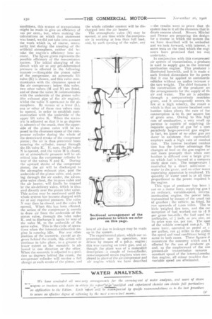
conditions, this system of transmission might be made to give an efficiency of too per cent., but, when making the calculations on which that statement was based, we did not take into account the work which is, of course, necessarily lost during the creating of the artificial atmosphere, neither did We take the engine's efficiency into account. The figure given represents the possible efficiency of the transmission system. The initial charging of the circuit with air at any pre-determined pressure is effected in the following manner :—Alongside the piston valve of the compressor, an automatic lift valve (K) is shown, and this valve communicates with the clearance space of the air compressor ; below this valve, two other valves (M and N) are fitted, and of these the valve M communicates with the underside of the piston valve (the exhaust pipe of the air engine), whilst the valve N opens out to the atmosphere. By means of a lever (L), one or other of these two valves may be opened, in order to establish communication with the underside of the upper lift valve K. When the eccentric is adjusted so that it is 90 degrees in advance of the crank, then the upper side of the piston valve will be exposed to the clearance space of the compressor cylinder during the whole of the downward stroke of the compressor piston ; the air is thus prevented from entering the cylinder, except through the lift valve K. If, now, the.lift valve N is opened, and the valve M is closed, air at atmospheric pressure will be admitted into the compressor cylinder by way of the valves N and K. During the upward stroke of the compressor piston, the air will be discharged to the air-engine exhaust pipe, past the underside of the piston valve, and, passing through the air cooler, the air-engine valve chest, the by-pass valve and the air heater, will finally be trapped by the air-delivery valve, which is situated directly over the piston inlet valve. This action may be continued until the whole system has become charged with air at any required pressure. The valve N may then be closed, and the valve M opened. When this has been effected, the action of the compressor is merely to draw air from the underside of the piston valve, through the inlet valve K, and to discharge it again by way of the valve M, to the underside of the same valve. This is the cycle of operations when the internal-combustion en gine is running idle. For any other position of the eccentric, except go degrees behind the crank, this action will continue to take place, to a greater or lesser extent as the eccentric is adjusted in one direction or the other. When the eccentric is adjusted to a position go degrees behind the crank, the compressor cylinder will receive a full charge at each stroke of the piston, and
the whole cylinder content will be discharged into the air heater.
The atmospheric valve (N) may be opened, at any time while the compressor is working at less than full load, and, by such opening of the valve, any loss of air due to leakage may be made up in the system. The experimental plant, which our representative saw in operation, was driven by means of a soh,p. engine; this was running on town gas, and although the plant was of a makeshift description—a couple of two-cylinder, non-compound steam engines were employed in place of the air compressor and air engine which we have described —the results went to prove that du system has in it all the elements that in dicate success ahead. Messrs. Mitchel and Dewar are preparing the design: for a tractor in which the system tha we have described will be embodied and we look forward, with interest, tc some tests on the road which the engi neers have promised that we man undertake.
In conjunction with this compressed air system of transmission, a produoeu is used to supply gas to the internal combustion engine. This producer illustrated herewith, and it is made o such limited dimensions for its powel that it can be applied to commercia vehicles without an undue increase o the tare weight. The chief features ii the construction of the producer an the arrangements for the supply of thl
air and water. The air is admittet through a comparatively restrietet grate, and it consequently enters du fire at a high velocity, the result o which is that an intense localised corn bustion takes place ; the rate of fue consumption is 6o lb. per square foo of grate area. Owing to this higl rate of combustion, a very small ap paratus is capable of supplying de requisite quantity of gas for a corn paratively large-powered gas engine in fact, we know of no other gas pre ducer in existence that successfull: employs such a high rate of combus don. The intense localised combus don has the further advantage tha changes of load on the gas engine ar met more promptly than when corn bustion is diffused over a large g-rat on which fuel is burned at a cornpara tively slow rate. The temperature i controlled by a direct admission water to the grate, and no other watet vaporising apparatus is employed. Th quantity of water used is at all time proportional to the power required b the engine.
This type of producer has been i use on a motor lorry, supplying gas t an ordinary, variable-speed, interne combustion engine, the power bein. transmitted by means of the usual typ of gearbox ; the vehicle, so fitted, ha run upwards of r,000 miles. The IN hick weighed five tons, and the cor sumption of fuel worked out to rf11 per gross ton-mile; the fuel used W.': anthracite, of inch, or pea size, an its price was los. per ton. The spee of the vehicle averaged iorn.p.h. TI same lorry, operated on petrol at i. per gallon, ran zi.; miles to the galloi the speed and road conditions being tF same in both cases. These figures d monstrate the economy which can effected by the use of producer ga and, as the employment of the con pressed-air transmission ensures constant speed of the internal-combu tion engine, all minor troubles due variable speed are eliminated.