


MAKING SE/ ILESS TUBES FROM S( ID BARS
Page 50
Page 51
Page 52
Page 53
If you've noticed an error in this article please click here to report it so we can fix it.
Tubes, Ltd., of Birmingham, Produe( Ranging from ,T1 in. to 15 ins. in D of Manufacture Makes A
Variety of Products, Including Tubes ter, and a Description of the Process mely Interesting Reading
IT Might safely be said of the "man in the street" that not one in 10 would associate the motor vehicle with the tube industry, • and hardly one in 100 realizes the important part that tubes and tubular prodtiets have to play in the manufacture of every bus or lorry to give satisfactory operation and safety. , Side by side with the improvements and refinements which have taken place in the development of steel manufacture, a research department has been conducted during recent years 'e by Tubes, Ltd., and its allied organizations. The company regards this department as one of the most important features connected with the manufacture of weldless-steel tubes.' It . steers a parallel • course with thesteel industry, in experimenting with materials, adopting only those steels and their allOys which are found to be most suitable.
In addition, the research department has established and maintained the closest contact with the engineers who are responsible for both the design and production of motor vehicles, and the resulting collaboration has been to the mutual benefit of the tube maker, ' the chassis designer and the motor user.
Before any raw material is put into use in the tube works, samples of every consignment are submitted to a• most rigorous and 'complete series of physical and chemical tests to determine their suitability.
The manufacture of long lengths of weldless or seamless steel tubes may seem somewhat of a mystery to those who have not had an opportunity for studying. the machinery involved or for seeing the pmcess in operation. The making of tubes by a method in which a heated strip of metal is drawn through a die and its edges welded together, is an -operation • which can be more easily understood, but the process by which a solid round bar of steel about 4 ins, in diameter and 3 ft. . long, is 'ccinverted in a few minutes into a weldless tube about 20 ft. long, in ono heat and with no waste of material, is one which cannot fail to arouse the curiosity of those who are interested in, mechanical problems and the conversion of raw materials into finished products.
All persons who have any connection with motor vehicles know the vital part that is played by highgrade weldless-steel tubes, which are used for axle tubes, torque tubes,. steering columns, outer, and inner rings for ball bearings and for even the yokes of magnetos, lighting dynamos and starters.
in describing this extremely, interesting process of manufacture, the works of Tubes, Ltd., of Birmingham, have been selected, as at these works can be
B32 The weldless tubes used in the construction of motor vehicles are made from steel billets of circular section, which, according to their size, are 'sawn or hydraulically broken into the lengths required for manufacture into tribes. These billets are then heated in large gasfired continuous-heating furnaces, in which they are thoroughly soaked at a temperature of abont 1,200-1,300 degrees C. It is essential that the heating of the billet should be gradual, in order to ensure that before it is worked the temperature from the core to the outer surface is uniform.
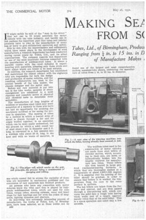
The hot billets are taken from the furnace and centred, and are then passed through a disc-piercing mill, which converts the solid into a rough tube having thick walls and of a length approximately twice that of the solid billet. This is a quick operation and takes only a few seconds. rotating discs. These discs turn in the same direction, but on account of their being disposed to one another, as shown in the diagrammatic view (Fig. 2), it will be seen that the billet is caused to rotate in the direction of the arrow. As the billet is introduced slightly below the centre of the discs, a screwing action is imparted to it which causes it to advance in a forward direction. At the opposite side of the piercing mill, a piercing plug, made from special steel which retains its hardness at high temperatures, is Situated. It is mounted; on a bar which is anchored at the end farthest from the billet, so that as the billet advances, the plug point engages with the centre. The faces of the discs are formed so that as the billet passes between them it is slightly corn, pressed, but as it advances still farther it is allowed to expand over the piercing plug, as shown:
Fig. 3 depicth the opposite side of the
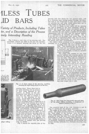
piercing mill and shows the hot pierced billet, still at a workable heat, havingpassed through the discs. The boss in the foreground is that part which holds the piercing bar and' plug,whilst spare bars can be seen cooling in the tanks on the right The tube, or bloom, is now taken off. the piercing bar and is passed. to the next operation, which is carried out by means of what are known as pilger roils. The pager -ruin works on the gap-roll principle, whereby the tube makes a number of successive engagements with the rolls, and the process consists of a combination . of swaging and rolling. • Fig. 4 is an end view of the pilger mill, whilst Figs. 5 and 7 give details of Individual pilger rolls, and, as will be seen from these illustrations, the rolls are,.cut away for nearly' half their circumference.
The hollow bloom produced on the piercing mill, is threaded on to a mandrel bar' of a diameter corresponding with the bore of the finished tube. This mandrel bar is attached to the front end of a feeder ; thiS can give it a backward and forward motion in the direction of its length, as well as a periodic rotary movement.
The' pilger mill consists of two rolls geared together and rotating against the direction in which the hollow bloom is fed into the rolls. The rolls are designed so that about only half of the circumference will engage the hollow bloom when it. is fed into the rolls, which we will call section X, the other half of the circumference being arranged to form a clearance space (section I"); and as they rotate section X automatically strikes the hollow bloom. The effect of this arrangement is to forge out a portion of the hollow bloom into a tube of pre-determined diameter and thickness, the mandrel bar acting as an anvil. Hy periodic rotation of the mandrel bar and suitable roll adjustment it is possible to feed the tube through the mill until the whole of the hollow bloom has been forged into a tube.
The eccentric part of the rolls between A and B (Fig. 7) carries out the swaging operation.
The origin of the word "pilger " is somewhat interesting. The pilger process originated in Germany and the word pilger is the German term for pilgrim. When approaching a shrine, it was the custom for pilgrims to take one step forwards and half a step backwards in order to prolong their approach. The tube, during the process of rolling, repeats this cycle of movement, oscillating backwards and forwards, but always moving definitely in a forward direction, step by step.
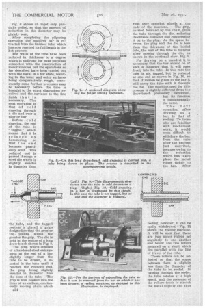
Fig. 0 shows an ingot only partially rolled, so that the amount of reduction in the diameter may be plainly seen.
After completing the pilgering operation the mandrel bar is extracted from the finished tube, which has now reached its full length in the hot process.
The walls of the tube have been reduced in thickness to a degree which is sufficient for most purposes connected with the construction of motor vehicles, but the operations so far described have been carried out with the metal in a hat state, resulting in the inner and outer surfaces being comparatively rough, consequently some further processes may be• necessary before the tube is brought to the exact dimensions required and the surfaces to the fine finish that is necessary. The next operation is that of c old drawing through a die and over a plug or bar.
Before cold drawing, the end of the tube is "tagged," which means that it is reduced by hammering, so that the end becomes practically solid. This reduced end is
passed through a steel die which is slightly smaller in diameter than the tube, and the tagged portion is placed in grips designed so that the greater the pulling strain the greater the grip. The die is held in the centre of a long draw-bench shown in Fig. 8.
The plug, which consists of a hardened-steel enlargement at the end of a bar slightly longer than the tube to be drawn, is inserted in the tube until it reaches the reduced end, the plug being slightly smaller in diameter than the bore of the tube. The grip is now hooked into the links of an endless, continuously moving chain which 534 runs over sprocket wheels at the ends of the machine, The grip, carried forward by the chain, pulls the tube through the die, reducing its outside diameter and compressing it on to the plug. As the space between the plug and the die is less than the thickness of the initial tube, the wall of the tube is reduced after passing through the die, as shown in the sectional view, Fig. 9.
For drawing on a mandrel it is necessary that the bar should be of sucha diameter that it. will pass -freely into the tube. In this case the tube is not tagged, but is reduced at one end as shown in Fig. 10, so that if motion be given to the bar it will carry the tube with it through the die. The machine used for this process is slightly different from the draw-bench previously mentioned, but its function is fundamentally
the same.
The next operation, after drawing on a bar, is that of reeling. To those who are familiar with mechanical work, it would seem difficult to withdraw the bar from the tube after the process just described, because owing to the reduction which has taken • place the metal clings tightly to the bar. After
reeling, however, it can be easily viith_drawit. Fig. 11 shows the reeling machine. It will be seen that there are two upper rollers set angularly to one. another and below are two rollers mounted on a shaft which lies parallel with the line of travel of the tube.
These rollers can be adjusted so that the space between them is slightly less than the diameter of the tube to be reeled. In passing through the reeler, the tube rotates at a high speed, and the pressure of. the rollers tends to stretch the metal slightly and thus relieve the pressure of the reduced tube on the bar, which enables the last-named to be easily withdrawn.
All cold-drawing operations have the effect of hardening the metal, therefore it is necessary that the tube should be annealed
between the passes. This is carried out in long gas-fired furnaces, and afterwards the tubes are placed in hot tanks of dilute sulphuric acid in order to remove all scale from both the inside and outside surfaces. ' Lubricant is applied to the tubes, internally and externally, during the process of cold-drawing.
They are now finally straightened by hand, this work being undertaken by experienced men who are specially trained.
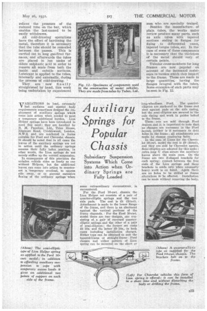
-Besides the manufacture.. of plain tubes, the 'works under review produce many parts, such as axle tubes with tapered sections ending in flanges for fixing to differential cases, tapered torque tubes, etc. In the case of some of these components It is necessary that the. thickness of the metal should vary at certain points.
Tubular cross-members for long frames are now -popular • ou account of the increaSed resistance to torsion which they impart to the frame. These are made in large quantities, having the flanges integral with the tubes. Some examples of such parts may beacon in Fig. 12.