Improving Wheel Grip
Page 44

If you've noticed an error in this article please click here to report it so we can fix it.
THE wheel-grip capacity of an axle of a bogie, when all four wheels are driven, is too well known to require recapitulation, but when one axle only , is used for transmitting the engine torque, matters are complicated somewhat under certain conditions of usage.
Typical of this state of affairs is the functioning of the Morris-Commercial. R.D. six-wheeler (or Bulk Load Carrier as it is better known) ; the .bogie, although, suspended in normal fashion, has only one pair of driving wheels. The third axle is arranged' so that it takes its full share of the load but is
merely a' " trailer." It will be seen, therefore, that at all times the driving wheels carry only half the load of a normal four-wheeled . chassis and, in consequence; when the , vehicle is running light, the permissible tractive effort which the tyres are capable of transmitting is.only -half that of,a fourwheeled vehicle working under similar
conditions. When partially or fully loaded, of course, plenty of wheel-grip is assured.
Such a contretemps can be very wasteful in time, despite the fact that a greatly increased load can be carried owing to the addition of the trailing
• axle.The following case will illustrate the point. A number of vehicles operating in a hilly district of Wales had to negotiate a steep decline when fully laden and in order to fetch another load had to climb the hill again. Owing to a very poor surface this was found to be impossible, and a detour of some dozen miles or so bad to be made in order to avoid the hill. Morris-Com.
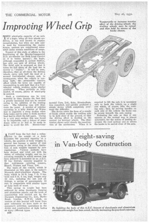
mercial Cars, Ltd., Soho, Birmingham, was consulted, and quickly produced a simple device which completely overcame the difficulty.
The device takes the form of acouple of hooks which enable the trailing axle to be held clear of the ground, so that the driving effort is doubled on the central (or driving) wheels. The illustration shows quite clearly the construction of the mechanism. When it is required to lift the axle it is necessaryonly to back the vehicle up a slight rise which, of course, lifts the trailing axle ; then, by moving handles on each side of the vehicle the hooks can be swung beneath the axle casing.
Releasing the axle so that it can operate in the normal way is almost automatic, for the action of loading depresses the road springs and so allows the hooks to be moved clear of the axle.


