


A Standard War-time Trolleybus Design
Page 24
If you've noticed an error in this article please click here to report it so we can fix it.
IT is generally known to trolleyhus 'operators that Karrier Motors, Ltd., and Sunbeam Commercial Vehicles. Ltd., are closely associated, and that Karrier and Sunbeam trolleybus chassis, whilst maintaining their individualities of design, are both manufactured in the same works. It will be well understood, therefore, that the special war-time chassis now being manufactured in the Sunbeam works incorporates the salient features of the Harrier E.4 and the Sunbeam M.F.2 two-axle types, both of which have been developed over a long period.
The special chassis now in production, vahich will be known as the NV-type, has behind it the accumulated experience of two manufacturers who have been connected with trolleybus design and production for many years past—the Karrier concern since 1926 and the Sunbeam company since 1931. Moreover, their vehicles are in use in nearly 30 towns at home and abroad.
Leading Municipal Buyers
Chassis have already been allocated, through the Ministry of War Transport, to the corporation transport departments of Belfast, Darlington, Reading, Maidstone, Wolverhampton, Walsall, Doncaster, Newcastle-on-Tyne, and Nottingham, as well as to the Mexborough and Swinton Traction Co., and the South kancashire Transport Co.
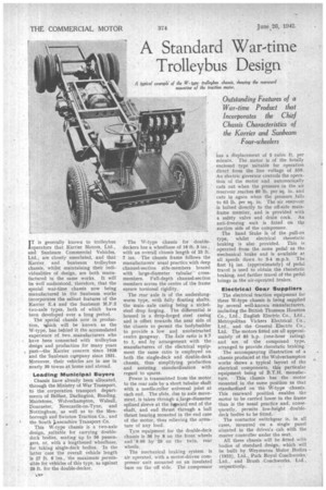
This W-type chassis is a two-axle design, ,suitable for carrying doubledeck bodies, seating up to 56 passengers, or, with a lengthened wheelbase, for taking single-deck bodies. In the latter case the overall vehicle length is 27 ft. 6 ins., the maximumpermissible for vehicles of this type, as against
26 ft. for the double-decker. ' age The NV-type chassis for doubledeckers has a wheelbase of 16 ft. 3 ins., with an overall chassis length of 25 ft. 7 ins. The chassis frame follows the manufacturers usual practice with deep channel-section side-members braced with large-diameter tubular crossmembers. Full-depth channel-section members across the centre of the frame ensure torsional rigidity.
The rear axle is of the underslungworm type, with fully floating shafts, the main axle casing being a nickelsteel drop forging. The differential is housed in a drop-forged steel casing and is offset towards the near side of the chassis to permit the bodybuilder to provide a low and unobstructed centre gangway. The axle ratio is 9.7 to 1, and by arrangement with the manufacturers of the electrical equipment the same ratio is employed on both the single-deck and double-deck chassis, thus simplifying production and assisting standardization with regard to spares.
Power is transmitted from the motor to the rear axle by a short tubular shaft with a needle-roller universal joint at each end. The slide, due to axle movement, is taken through a large-diameter splined sleeve at the favard end of the -shaft, and end thrust through a ball thrust bearing mounted in the end case of the motor, thus relieving the armature of any load.
Tyre equipment for the double-deck Chassis is 36 by 8 on the front wheels and '.9.00 by 20 on the twin, rear wheels.
The mechanical braking system is air operated, with a motor-driven compressor unit mounted on an insulated base on the off side. The compressor has a displacement of 5 cubic ft. per • minute. The motor is of the totally enclosed type suitable for operation direct from the line voltage of 550. An electric governor controls the operation of the motor and automatically • cuts out when the pressure in the air reservoir reaches 80 lb. per sq. in. and cuts in again when the pressure falls to 65 lb. per sq. in. The air reservoir is bolted directly to the off-side mainframe member, and is provided with a safety valve and drain cock. An anti-freezing unit is fitted on the suction side of the compressor.
The hand brake is of the pull-on type, whilst electrical rheostatic braking is also provided. This is operated from the same pedal as the mechanical brake and is available at all speeds down to 3-4 m.p.h. The first l ins. (approximately) of pedal travel is used to obtain the rheostatic braking, and further travel ofthe pedal brings in the air-operated brakes.
• Electrical Gear Suppliers The electrical traction equipment for these W-type chassis is being supplied by several well-known manufacturers, including the British Thomson Houston Co., Ltd., English Electric Co., Ltd., Metropolitan Vickers Electrical Co.. Ltd., and the General Electric Co.. Ltd. The motors fitted are all approximately of 85 h.p. (one-hour rating) and are of the compound type, arranged to provide rheostatic braking: The accompanying illustration of a chassis produced at the Wolverhampton works shows a typical layout of the electrical components, this particular equipment being of B.T.H. -manufacture. Thia chassis has the motor mounted, in the same position as that standardized on the W-type -chassis. This rearward position enables the' motor to be carried lower in the frame than is the usual practice and, consequently, permits low-height double. deck bodies to be fitted.
The contactor switchgear is, in all cases, mounted on a single panel • situated in the drivers cab with the master controller under, the seat.
All these chassis will be fitted with bodies of standard design, which will be built by Weymanns Motor Bodies • (1925), Ltd., Park Royal Coachworks,. Ltd., and Brush .Coachworks, Ltd.. respectively.