


HINTS ON MAINTENANCE.
Page 26
Page 27
If you've noticed an error in this article please click here to report it so we can fix it.
How to Get the Best Out of a Vehicle, to Secure Reliability and to Avoid Trouble.
391.—How to Reinforce Laminated Springs.
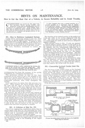
Useful advice concerning springs is not very often available, as spring, makers and repairers are somewhat conservative in this respect: A spring is often looked upon as something which must be treated as a mystery only to be solved by afew persons who have followed the springsmith's trade from their youth. We were, therefore, interested to receive the accompanying hint from the manager of the spring department of a well-known manufacturer. This gentleman informs us that he has been requested several times to say if the bending of the leaves of a spring round the eyes, as shown at the left of the spring which we illustrate in its free and compressed positions, does really strengthen the springs.
From experience he states that this prevents free action. When loaded, the leaves become locked at the ends and the upper is forced away from the second, as shown in the lower figure of the illustration. It is, therefore, obvious that the extra stress on the top leaf tends towards fracturing at the points where the upper spring forms a hump.
If, however, the end of the second leaf, instead of being turned right round the eye, is carried only halfway round it. then when the spring deflects the end of the second plate is merely forced away from the eye in the manner shown in the illustration of the spring in its compressed position, thus preventing the ends from being locked. At the same time, this half-turn of the second leaf round the eye helps to strengthen it and, in the ease of fracture of the top leaf, will support the load until the garage is reached.
392.—A Criticism of Hint No. 379.
One of our engineering contributors states that he cannot agree with Hint No. 379 concerning the TYlor engine so far as the function of the tappet guide at the slotted end is concerned, and likewise with the method to be employed to adjust the tappet.
He has never yet known of a case where a roller has become detached from the tappet and has fallen into the crankcase owing to the breaking of the tappet guide fork ends.
B44
The function of the slotted portion of the guide is to retain the iofler in its correct alignment with the cam. The roller pin is pressed into the tappet and two centre pops are made at each end as a safeguard against it shifting.
What actaally occurs is this. If only one spanner be used to adjust a tappet, whether on the head or on the lock-nut, the fork ends have to resist the pull of the spanner and are consequently subjected to a shearing action and often break, with the result that the tappet can then turn, and it has a natural tendency to work across the cam, i.e., the tappet turns to 90 degrees from its correct position. The cam is then invariably gouged out, as the roller surface is harder than that of the cam, the result being that in most eases the camshaft has to be replaced.
The whole of the trouble can be obviated by using two thin spanners, one on the tappet head and the other on the locknut. These are employedagainkt each other when loosening or tightening the locknut, and thus remove the stress from the guide.
393.—Concerning Leyland Cardan Joint Die Boxes.
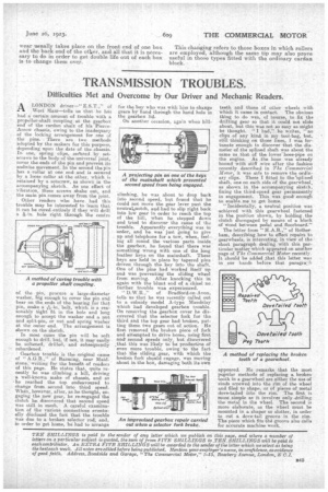
The die boxes of the cardan joints on the Leyland chassis are subjected to a considerable amount of stress during the whole of the time a vehicle is in operation. Consequently, wear takes place, and after a great deal of service i
it is usually necessary to renew them, as the slackness causes a very objectionable rattle, particularly if the joints are not well lubricated. 'These boxes are fairly expensive. They are, therefore, very often 1' MI in bad condition until their replacement is enforced.
If the die boxes are examined it will be noticed that wear -usually takes place on the front end of one box and the back end of the other, and all that it is necessary to do in order to get double life out of each box is to change them over.
This changing refers to those boxes in which rollers are employed, although the same tip may also prove useful in those types fitted with the ordinary cardan block.