


EQUIPPING A COACH FOR WIRELESS RECEPTION.
Page 20
Page 21
If you've noticed an error in this article please click here to report it so we can fix it.
The Choice of a Suitable Set and its Appurtenances, and its Installation on the Vehicle.
IN THE three articles which have already appeared in The Commercial Motor on this subject, we ' have covered the question of installi,ng the aerial and the lead-in and of ensuring the fullest possible insulation for the weak currents to which our aerial is capable of responding.
Choosing the Set.
The next point to consider is the choke of a set and its actual installation•on the vehicle: We must also consider the choice and care of the appurtenances to the set proper, such as valves, 'phones, loud speaker, accumulators, and high-tension batteries. Let us consider the set first.
If one looks over the advertisement pages of any of the periodicals devoted to wireless, one is likely to be bewildered by thc number and variety of the sets that are offered for sale. The choice is overwhelming and the prices vary in such a bewildering manner that one is almost at a loss to know where to begin. At the outset, therefore, in radio, just as in anything else, it is well to bear in mind that if one wants reliable apparatus one must be prepared -to pay a fair price for L. It is often difficult to see exactly where the difference in the value between a well-made set by a reputable maker and a mediocre one by a less well-known firm comes in. But, in elecirical work, so much depends on the care exercised in manufacture, and such a great deal of the work is hidden, that it is short-sighted policy to buy cheap stuff. In fact, experienced electricians have coma to look upon cheapness in such gear as a suspicious sign. One should, therefore, use the greatest. caution, and only buy after assuring oneself that. low cost is not due to skimped manufacture.
Receiving sets may be divided into two great classes at the present time crystal sets and valve sets. The crystal set, although excellent for reception over short distances, is useless for our purpose owing, firstly, to the restricted nature of our aerial, and, secondly, to the ever-varying distances at which we shall require reception. So we will content ourselves by remarking in passing that, to those who have had no jireviouS experience of radio and who can erect a fairly good outdoor aerial at their homes; the simple crystal set offers the best means of practice for the handling of the more complicated and, in inexperienced hands, the more interfering valve set..
For our purpose, them, we must employ a valve receiver, and before describing any particular set we will sav a word on the different ways in which the thermionie valve may be employed in wireless reception.
The Functions of the Valve.
In the article that appeared in The Commercial Motor for February 20th (one of the first series on wireless recention on vehicles), we very sketchily outlined the principle on which the valve worked. We do not propose to go over that ground again, but would refer new readers to the article in question if they have any difficulty in following the explanations to came. Suffice here, to say that the valve may be employed in three different and distinct ways and that most receivers use a combination of these ways of valve usage to effect their purpose. The methods of employing a valve are :—(1) As a high-frequency amplifier ; (2) as a detector ; and (3) as a low-frequency or note magnifier.
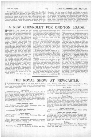
Study Fig. 1. This gives the circuit diagram of a simple receiver in which the valve acts as a detector only. One will notice that it consists of an inductance (L), across which are connected the grid and lila .838 ment of 'a valve (V). The inductance is tuned by means of a variable condenser (Cl). In the plate circuit. of the valve is a high-tension battery (B2) and the telephones (T). The battery (131) heats the filament of the valve., and thus makes it function. The brightness of the filament is controlled by means of the variable resistance (R1).
By what has already been said on the method of operation of a valve, it will be readily understood that, if an alternating potential be applied across• the inductance (L), it will render the grid of the valve alternately positive and negative, which will result in unidirectional pulses of current in the plate circuit of the valve, these pulses keeping time with the alternations across. the inductance. As hqwever, our alternations are received from the aerial (A) and are what are known as high-frequency oscillations, which means that they may have a frequency all the way from 50,000 a second up to over 1,000,000 a second, it will be quite impossible for the telephones (T) to respond to them unless we make use of some additional apparatus. We overcome the difficulty by inserting in the grid circuit a small fixed condenser (02); which has the effect of causing the valve output current no longer slavishly to resemble the input oscillations, but to be, as it were, lopsided--that is, to be more positive than negative.
The Need for Condensers and a Grid Leak.,
As .a result, the telephones can respond to the difference between the positive and the negative • sides of the oscillation just as if it were a small direct current, so that any slaw speech Modulation that may be superimposed on the high-frequency oscillations will be able to make its effect heard. Since this effect is dependent on true static inductance across the condenser (02), and since the first charge received from the aerial will charge the condenser, and, subsequently, it will only partially be discharged at each alternation, unless some provision is made for getting rid of the unwanted charge, the full efficiency of the device cannot be enjoyed. To overcome this difficulty, we connect a high resistance— about 2,000,000 ohms—and marked R2 in the figure, across the condenser, and this allows the condenser to become setnewhat leaky and the unwanted charges to leak away to earth.If all is adjusted well, the condenser will just free itself in between subsequent signals.
Since high-frequency pulses—although lopsided ones—will still be flowing in the plate circuit, and since the amount of iron in the telephones and the number of turns of wire in their coils render selfinductance 'very high, it has been found that the 'phones tend to block the passage of these high-frequency currents, with a result that they try to get through via the wearer's head and body to earth. In' order to keep them out of the telephones as much as possible, these latter are shunted by a condenser (C3), which, by offering a practically free path to these h.-f. currents, diverts them, without, at the same time, reducing the amount of slow-frequency speech currents that go to make the 'phones sound.