


BALANCING RECIPROCATING ENGINES.
Page 28
If you've noticed an error in this article please click here to report it so we can fix it.
A Resume of Recently Published Patent Specifications.'
-LiW. LANCHESTER describes in
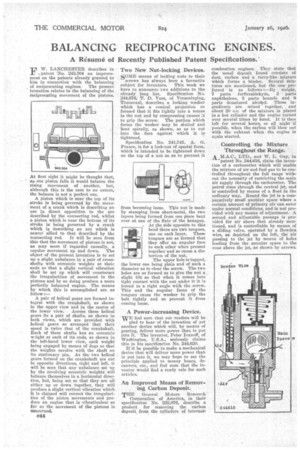
-.patent No. 243,304 an improvement on the patents already granted to hint in connection with the balancing of reciprocating engines. The present invention relates to the balancing of the reciprocating movement of the pistons.
At first sight it might be thought that, as one piston falls it would balance the rising movement of another, but, although this is the case to an extent, the balance is not a perfect one.
A piston which is near the top of its stroke is being governed by the movement of a crank which is describing an arc in direct opposition to the arc described by the connecting rod, whilst a piston which is near the bottom of its stroke is being governed by a crank which is describing an arc which is mare:, allied to that described by the connecting rod. it will be seen from this that the movement of pistons is not, as may seem if 'regarded casually, a regular movement up and down. The object of the present invention is to set up a slight unbalance in a pair of crossshafts with eccentric weights at their ends so that a slight vertical vibration shall be set up which will counteract the irregularities of movement in the pistons and by so doing produce a more perfectly balanced engine. The means by which this is accomplished are as follow:— A pair of helical gears are formed integral with the crankshaft, as shown in the upper view and in the centre of the lower view. Across these helical gears lie a pair of shafts, as shown in both views, which are provided with helical gears so arranged that their speed is twice that of the crankshaft. Each of these shafts has an eccentric w2ight• at each of its ends, as shown in the left-hand lower view, each weight being engaged by means of dogs so that the weights revolve with the shaft on its stationary pin. As the two helical gears formed on the crankshaft are cut in apposite directions, right and left, it will be seen that any unbalance set up by the revolving eccentric weights will balance themselves in a horizontal direction, hut, being set so that they are all either up or down together, they will produce a slight vertical vibration which it is claimed will correct the irregularities of the piston movements and product an engine that is vibrationless so far as the movement of the pistons is concerned.
Two New Nut-locking Devices,
SOME means of locking nuts to their
screws has always been a favourite subject for inventors. This week we have to announce two additions to the already long list. Specification Na. 244,676, T. D. Vass, of Verse/ringing, Transvaal, describes a locking washer which has a conical projection el) formed that it fits tightly into a recess in the nut and by compressing causes it to grip the screw. The portion which forms the washer may la-t slotted and bent spirally, as shown, so as to cut into the face against which it is tightened.
Specification No. 241,:541, A. G. France, is for a lock-nut of special form, which is intended to be tightened down on the top of a nut so as to prevent it from becoming loose. This nut is made
by stamping from sheet-metal, the two layers being formed from one piece bent over at one of the flats of the hexagon. At the side opposite to this bend there are two tongues, one on each layer. These tongues are so formed that they offer an angular face to each other when pressed together and so cause a distortion of the nut.
The upper hole is tapped, the lower one being plain and of such a diameter as to clear the screw. The two holes are so formed as to give the nut a , slight tilt so that when it comes into tight contact with the nut under it it is forced to a right angle with the screw. This and the angular faces of the tongues cause the washer to grip the bolt tightly and so prevent it from coming loose.
A Power-increasing Device.
WE feel sure that oar readers will be glad to bear of the invention of yet another device which will, by means of gearing, deliver more power than is put into it. • The inventor, Peter Ivanoff, of Washington, U.S.A., seriously claims this in his specifination No. 244,620.
If it be possible to make a mechanical device that will deliver more power than is put into it, we may hope to see the principle applied to money boxes, decanters, etc., and feel sure that the inventor would find a ready sale for such articles.
An Improved Means of Removing Carbon Deposit.
THE General Motors Research Corporation of America, in their specification No. 222,076, describe a product for removing the carbon deposit from the cylinders of internal combustion engines. They state that the usual deposit found consists of dust, carbon and a tarry-like mixture which forms a binder. Several mixtures are mentioned, but the one preferred is as follows :—By weight, 7 parts furfuraldehyde, 3 parts naphthalene, S parts benzoic and 6 parts denatured alcohol. These ingredients are mixed together, and about 20 c.c. of the mixture is placed in a hot cylinder and the engine turned over several times by hand. It is then left for several hours, or all night if possible, when the carbon will blow out with the exhaust when the engine is again started.
Controlling the Mixture Throughout the Range.
LTD., and W. L. Guy, in
patent No. 244,610, claim the invention of a carburetter which will enable the mixture of air and fuel gas to be controlled throughout the full range without the necessity of restricting the main air supply through the carburetter. The petrol rises through the central jet, and is controlled by means of a float iu the ordinary way. Round the jet is a comparatively small annular space where a certain amount of primary. air can enter under, normal conditions, and is not provided with any means of adjustment. A second and adjustable passage is provided for air above that already mentioned, and is controllable by means of a sliding valve, operated by a Bowden wire, as depicted on the left, the air passing to the jet by means of holes leading from the annular space to the cane above the jet, as shown by arrows.