


Patents Completed.
Page 20
If you've noticed an error in this article please click here to report it so we can fix it.
Complete specifications of the following patents will be sent to any address in the United 'Kingdom upon receipt of eightpence per copy at the Sale Branch, Patent Office, Holborn, W.C.
VALVELESS PUMP. — Lamplough and Son, Ltd.—No. 60, dated let January, 1910.—The pump described in this specification consists of a cylindrical casing provided with inlet and outlet ports, and having, rotatably mounted within it, a yoke divided into two parts for a double-acting pump, or without the division for a single-acting pump. In this space (d) there is fitted a piston (e) su:tably curved and capable of longitudinal motion. Bushes are formed in the piston to be engaged by a pin which is carried upon a ring eccentrically mounted in the end casing. As the yoke revolves, it carries the piston and this ring round with it, and, owing to the eccentricity of the ring, the piston is given a reciprocating motion. This motion is adapted to give the suction and exhaust as the piston travels between the inlet and the outlet. The feature of this
pump is, that, as there are two pistons, a quadruple action is obtained. [The Lamplough pump was first illustrated in our issue of the 15th September, 1910.— En.]
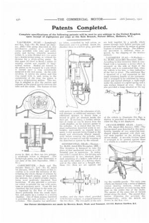
CARBURETTER. — Bush and The Daimler Motor Co. Ltd.—No. 67, dated 1st January, 1910.—The object of this invention is to avoid the necessity of distributing the whole charge of mixture by means of branch piping, and to permit the mixture, for a multi-cylinder engine, being more positively regulated than heretofore. It also provides a carburetter which is suitable for use with petroleum or petroleum spirit From the fuel ehambers the fuel passes to the main jet, is vaporized by the flow of warm air drawn preferably from the crank chamber, and passes up a conduit to a mixing chamber. One of these mixing chambers is provided for each cylinder, Or pair of cylinders. This chamber has additional
air inlets, controlled by ball valves, as illustrated, and it is jacketed. Inside the chamber there is a hollow plug, provided with ports to control the admission of air, rich mixture, or additional mixture; this additional mixture is drawn from a second or pilot jet situated beside the main jet. If necessary, a further admixture of warm air can be drawn from the crank chamber, as the mixture passes to the cylinder. It is stated that the twostage earburatiun described tends to uniformity,, particularly as regards heavy spirit, a rich mixture being formed at the nozzle and afterwards diluted immediately before entering the cylinder with the use of warmed air and the warming of the distribution system by the exhaust.
DIFFERENTIAL GEAR.—Thomas.— No. 30,318, dated 28th December, 1909.— This invention is designed to take the place of that mechanism known as a differential gear in motorcars. In motorcars with a central drive, the driving axle is constructed in two identical parts, each consisting of a hollow tube fixed at one end to the centre of a driving wheel, and at the other end to a flanged disc ; these two discs are set against one
another, and the chain wheel, provided with friction surfaces, is gripped between the two discs. The two parts of the axle are held together by a spindle which passes through both hollow portions and presses them together by means of spring washers of suitable design. The differential movement is obtained, when re quired, by the slipping of the friction surfaces.
TAXIMETER FLAG.—McKechnic.— No. 30,407, dated 29th December, 1900.— According to this invention there is combined with a taximeter a device which is arranged on the side or front of the vehicle, and is so constructed that, when the vehicle is for hire, a clear indication of the fact is given. The additional flag is mounted on a rod connected to the usual actuating handle of the taximeter, and is arranged to be exhibited by being raised and turned through a right-angle under the control of a spiral spring and a cam surface formed of wire. There is also provided a lamp situated on the top
of the vehicle to illuminate this flag ; a shutter is provided to obscure the lamp when the flag is not displayed.
CHANGE-SPEED GEAR.—Austin.No. 974, dated 14th January, 1910.—The change-speed gear described in this specification consists of two somewhat-coneshaped wheels mounted with their narrow ends together on the driving and driven shafts. A movable friction wheel is arranged to be pressed against these two wheels in a number of positions, giv ing the variable speeds. The main cone wheels are formed with a series of distinct conical bearing surfaces, which are irustra, of a number of cones having their axes on the centre line of the shafts. The apexes of the cones line at various points along the shaft. The second illustration illustrates the principle diagrammatically, while the details are shown in the first view.