 1
1 2
2 3
3 4
4 5
5 6
6 7
7 8
8 9
9 10
10 11
11 12
12 13
13 14
14 15
15 16
16 17
17 18
18 19
19 20
20 21
21 22
22 23
23 24
24 25
25 26
26 27
27 28
28 29
29 30
30 31
31 32
32 33
33 34
34 35
35 36
36 37
37 38
38 39
39 40
40 41
41 42
42 43
43 44
44 45
45 46
46 47
47 48
48 49
49 50
50 51
51 52
52 53
53 54
54 55
55 56
56 57
57 58
58 59
59 60
60 61
61 62
62 63
63 64
64 65
65 66
66 67
67 68
68 69
69 70
70 71
71 72
72 73
73 74
74 75
75 76
76 77
77 78
78 79
79 80
80 81
81 82
82 83
83 84
84 85
85 86
86 87
87 88
88 89
89 90
90 91
91 92
92 93
93 94
94 95
95 96
96 97
97 98
98 99
99 100
100 101
101 102
102 103
103 104
104 105
105 106
106 107
107 108
108 109
109 110
110 111
111 112
112 113
113 114
114 115
115 116
116 117
117 118
118 119
119 120
120 121
121 122
122 123
123 124
124 125
125 126
126 127
127 128
128 129
129 130
130 131
131 132
132 133
133 134
134 135
135 136
136 137
137 138
138 139
139 140
140 141
141 142
142 143
143 144
144 145
145 146
146 147
147 148
148 149
149 150
150 151
151 152
152 153
153 154
154 155
155 156
156 157
157 158
158 159
159 160
160 161
161 162
162 163
163 164
164 165
165 166
166 167
167 168
168 169
169 170
170 171
171 172
172 173
173 174
174 175
175 176
176 177
177 178
178 179
179 180
180 181
181 182
182 183
183 184
184 185
185 186
186 187
187 188
188 189
189 190
190 191
191 192
192 A Universal Loading Ramp
Page 62
If you've noticed an error in this article please click here to report it so we can fix it.
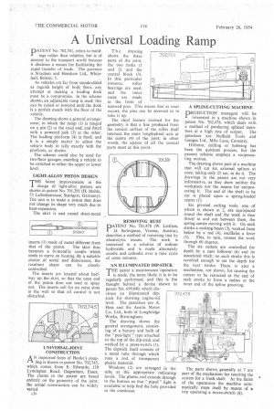
DATENT No. 702,701, refers to build
ings rather than vehicles, but is of interest to the transport world because it discloses a means for facilitating the rapid transfer of loads. The patentee is Strachan and Henshaw Ltd., Whitehall, Bristol, 5.
As vehicles are far from standardized as regards height of body floor, any attempt at making a loading dock must be a compromise. In the scheme shown, an adjustable ramp is used; this can be raised or lowered until the dock is a perfect match with the floor of the vehicle.
The drawing shows a general arrangement, in which the ramp (1) is hinged on a pin (2) at the road end, and fitted with a powered jack (3) at the other. The loading platform (4) is fixed, and it is a simple matter to adjust the vehiee body to tally exactly with the platform, as shown.
The scheme could also be used for two-floor garages, enabling a vehicle to be switched to either the upper or lower level.
LIGHT-ALLOY PISTON DESIGN
THE latest improvements in the design of light-alloy pistons are shown in patent No. 701,291 (H. Mahle, 73 Leibnitzstrasse, Stuttgart, Germany). The aim is to make a piston that does not change its shape very much due to heat-expansion.
The skirt is cast round sheet-metal inserts (1) made of metal different from that of the piston. The skirt thus becomes a bi-metallic couple which tends to curve on heating. By a suitable choice of metal and dimensions, the resultant shape can be closely controlled.
The inserts are located about halfway up the skirt, so that the open end of the piston does not tend to splay out. The inserts call for no extra slots in the wall so that oil control is not 'disturbed.
AN improved form of Hooke's coupling is shown in patent No. 702,745, which comes from E. Edwards, 139 Lymington Road, Dagenham, Essex. The claims in the patent are based entirely on the geometry of the joint; the actual construction can be widely varied.
T h e drawing shows the three parts of the joint, the two forks (I and 2) and the central block (3). In this particular instance, roller bearings are used, and the inner races are made in the form of screwed pins. This means that as wear occurs, the pins can be screwed in to take it up.
The chief feature claimed for the geometry is that a line produced from the conical surface of the roller shall intersect the main longitudinal axis at the centre (4) of the joint; in other words, the apexes of all the conical parts meet at this point.
PATENT No. 701,478 (W. Lettfuss, 14 Seilergasse, Vienna, Austria), describes a method of removing rust by electrolytic means. The work is immersed in a solution of sodium hydroxide and is made alternately anodic and cathodic over a time cycle of some minutes.
AN ILLUMINATED DIP-STICK THE easier a maintenance operation I is made, the more likely it is to be i regularly performed, and this s the thought behind a device shown in patent No. 699,840, which discloses an illuminated dipstick for showing engine-oil level. The patentees arc A. Hess and the Austin Motor Co., Ltd., both of Longbridge Works, Birmingham.
The drawing shows the general arrangement, consisting of a battery and bulb of the " pen-light " type attached to the top of the dip-stick and worked by a press-switch (I). The dipstick itself consists of a metal tube through which runs a rod of transparent plastic material.
Windows (2) are arranged in the tube at the appropriate indicating levels. The plastic rod extends through to the bottom so that " piped " light is available to help find the hole provided in the crankcase. A SPLINE-CUTTING MACHINE
PRODUCTION managers will be interested in a machine shown in patent No. 702,478, which deals with a method of producing splined members at a high rate of output. The patentees are Nuffield Tools and Gauges Ltd., Mile Lane, Coventry.
Hitherto, mining or hobbing has been the quickest process, but the present scheme employs a reciprocating motion.
The drawing shows part of a machine that will cut six external splines at once, taking only 25 sec. to do it. The drawings in the patent are not very informative, as they show neither the workpiece nor the means for reciprocating it. The end of the shaft to be cut is placed upon a spring-loaded centre (1).
Six pivoted cutting tools, one of which is shown at 2, are equispaced round the shaft and the work is then thrust in and out between them, the spring centre moving with it. On each stroke a rocking beam (3), worked from below by a rod (4), oscillates a lever (5). This, in turn, rotates the work through 60 degrees.
The six cutters are controlled for depth by a cam follower (6) and its associated track; on each stroke this is revolved enough to set the depth for the next stroke. There is also a mechanism, not shown, for causing the cutters to be retracted at the end of each stroke to form a radius at the inner end of the spline grooving.
The parts shown generally at 7 are part of the mechanism for resetting the cutters for a fresh shaft. At the finish of the operations the machine automatically stops itself by means of a trip operating a micro-switch (8).