


Battery-electric Chargeable From Any Mains Supply
Page 34
If you've noticed an error in this article please click here to report it so we can fix it.
GEITERALLY speaking, the outward range of a battery-electric vehicle is hunted to one half of its total storage capacity, the other halt being reserved for the homeward run. This disadvantage could be removed by the establishment of additional charging stations, but to do so might be impracticable on promiscuous routes. A solution is suggested in patent No. 549,784, which describes a batterydriven , vehicle complete with its own charging system, operable at any place where a mains supply is available. The patentee is Allrnanna Svenska. Elektriska A.B., Vasteras, Sweden.
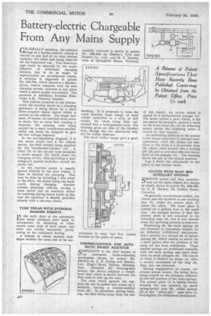
This concern proposes to use alternatively the traction motor as a charging generator, it being driven by a small direct-coupled mains motor which is carried on the vehicle. The larger unit must, Of course, be switched from series to shunt, but no extra field winding is required, the existing coils being excited by a small transformer-rectifier which can easily be designed to give the loW voltage required.
In the .accompanying diagram, 5 is the mains motor and 4 the vehicle motor, the field current being supplied by the transformer-rectifier (1). A relay (3) of the cut-out type energizes a mains magnet (2) which closes the charging circuit, thus providing a dual safeguard against back-flow should the mains fail.
As the traction motor is usually geared directly to the road wheels, it must be isolated for charging. This may be done by including a free wheel in the drive, the motor being run backwards during charging. 'Another scheme mentions vehicles having a main motor and an auxiliary motor for assisting during heavy loads; in this case the auxiliary is ifsually provided already with a one-way clutch.
TYRE TREAD WITH INTEGRAL HARDER INSERTS
IN the early days of the pneumatic tyre many attempts were made to incorporate by moulding or other means some form of hard insert, hut • none was wholly successful, partly owing to the continued flexing.
A scheme in which modern technique enables the same end to be sac
cessfully achieved is shown in patent No. 549,904 by Henley's Tyre and Rubber Co., Ltd., and H. T. Stanley, both of Springfield House, Westcott,
Dorking. It is proposed to form the tread mixture from lumps of hard rubber embedded in a strip of soft rubber, the whole being then vulcanized into a homogeneous mass. The drawing gives an idea of the finished tyre, though the two substances may not be visibly different. .
The hard rubber -lumps give a good
THERMO.CONTROL FOR AUTO. TvIATIC BRAKE ADJUSTER QIMPLICITY is the chief feature of an automatic brake-adjusting mechanism shown in patent No. 549,914 by J, S. Irving and Bendix, Ltd., KinA's Road, Tyseley, Birmingham. Intended for floating-shoe brakes, the device employs a conedhead stud which is forced between the shoe ends to take up the wear.
The cone which spreads the tappets (6) can be pulled into action by a setscrew, having a ratchet-toothed head (5). In operation, during braking, the shoe floats away from the end of the tappet, an action which is copied by a spring-loaded plunger (1). The latter carries a pawl which, if the movement be excessive, gathers a tooth on the screw head (5); on the following return stroke the adjusting screw is turned by tharamount.
An interesting addition to the system is the means employed to prevent overadjustment when the drums are hot. Close to the drum is a bi-metallic strip (4) which, when heated, lifts a locking pin' (3) and so prevents effective movement of the plunger (1) . The drawing shows the pin in the heated position.
Lug 2 limits the adjustment to the pitch of 'one ratchet tooth.
CLUTQ-I WITH MAIN 11IND AUXILIARY SPRINGS QMOOTH action and easy manufac ture are the main objects of a design of clutch shown in patent No. 549,396, by G. E. 'Stanley, 92, Godiva Street, Coventry.
Of generally conventional outline, the clutch uses the flywheel as one working face (7), whilst the presser plate (1) forms the other. The inner plate is carried on a splined boss in the usual way. An unusual feature is that the presser plate is not attached to its actuating ring (4), but is free thereof when the operating pressure is•removed.
Numbering 16, the main springs (3) are retracted in customary manner by an orthodox withdrawal mechanism, but a novelty is a second set of lighter springs (8), which remain in action for a short period after the pressure of the main set has been withdrawn. These smaller springs are positioned coaxially with the main springs and exert their force on small plungers (5). The travel of these is limited by stops,so, after a certain movement of. the ring (4), they, too, are retracted.
During engagement, .of course, the reverse action occurs, the initial drive being created by the plungers, followed by the full pressure of the main springs. The presser plate (1) is lightly loaded towards the free position, by small spring-loaded pins (6), whilst springs (2) of the "safety-pin " type serve to load slightly the withdrawal mechanism.