


Collier and Operator Evolve New Gas-producer Design
Page 33
If you've noticed an error in this article please click here to report it so we can fix it.
A Compact Unit with Attractive Features Representing a Joint Effort by a Well-known Anthracite Company and a Road transport Concern
SustpLicity and improved efficiency are claimed for a producer-gas plant designed by Amalgamated Anthracite
Collieries, Ltd., Dxchange Buildings, Swansea, the supplier of Progasite, and
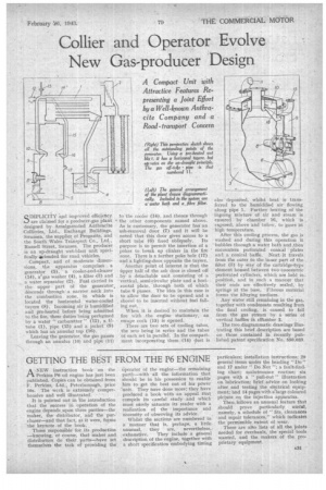
the South Wales Transport Co., Ltd.., Russell Street, Swansea. The producer is an up-draught wet-blast unit specifically 40itended for road vehicles. Compact, and of moderate dimensions, the apparatus comprises a generator (5), a cooler-and-cleaner. (14), a:/gas washer (4), a filter -(3) and . a water separator (2). Fuel Carried in the upper part of the generator,
descends through a narrow neck into the combustion zone, in whichis located the horizontal water-cooled tuyere (8). Incoming air is humidified and prerheated before being admitted to the fire, these duties being performed by a water " carburetter " (12), a .U• tube (1), pipe (15) and a jacket (9) which has an annular top (16).
Leaving the generator, the gas passes through an annulus (10) and pipe (11) to the cooler (14), and thence through • the other components named above. As is customary, the generator has an ash-removal door (7) and it will be noted that this door gives access to a
short tube (6) fixed obliquely. Its purpose is to permit the insertion of a poker to break up clinker in the fire 'zone. There is a further. poke hole (17) and a lighting-door, opposite the tuyerc.
Another point of interest is that the tipper half of the ash door is closed off by a detachable unit consisting of a 'vertical, semi-circular plate and a horizontal plate, through both of which tube 6 passes. The idea in this case is to allow the door to be opened and a , shovel' to be inserted without fuel falling out.
When it is desired to maintain the fire with the engine stationary, an escape cock (13) is opened.
There are two sets of cooling tubes, the sets being in series and the tubes of each set in parallel. In the compartment incorporating them -(14) slust is also deposited, whilst heat • is transferred to the humidified air flowing along pipe 1. Further heating of the ingoing mixture of air and steam is ensured by chamber 16. which is exposed, above and below, to gases at high temperature.
After this cooling process, the gas is washed and during this operation it bubbles thiough a water bath and ,then encounters perforated conical plates an1 a conical baffle. Next, it travels from the outer to the inner part of the filter (3) by way of the c,artridge-type element housed between two 'concentric perforated cylinders, which are held in. position, and in such a manner that their ends are effectively sealed, by springs at the base. Fibrous material forms the filtering medium.
Any water still remaining in the gas, together with condensate resulting from the final cooling, is caused to fall from the gas stream by a series of vertical baffles in clfamber 2.
The two diagrammatic drawings illustrating this brief description are based on those contained in recently published patent specification No. 550,033.