


A CHASSIS WITHOUT A FRAME.
Page 30
If you've noticed an error in this article please click here to report it so we can fix it.
A Résumé of Recently Published Patents.
miTEItIa are many interesting features -1..-about the chassis which is described, in specification No. 20%471, by J. Weller, apart from the fact that its con-. struction is most nnu.sual in that it has no frame. Constructors and users of agricultural tractors are more or less well acquainted with the principle involved, which dispenses with the usual :separate structural steelwork and makesthe engine, gearbox and rear axle perform the function usually set apart for the frame. In a vehicle in which the reaX axle is sprung the precise schedule set OM above, as applying to an agricultural tractor, is, of course, impossible, but this designer goes as near to it as maybe bv making the engine, gearbox and a tutrulat 'prolongation of the latter serve as the frame, the connection between it and the rear axle being the familiar spherical-ended tubular torque rod. The length of this "backbone," as it might be called, is about two-thirds that of the chassis ; the front of the engine case is approximately in line with the front axle, -whilst the tubular extension of the gearbox terminates at a, point about two-thirds of the distance towards the rear axle.
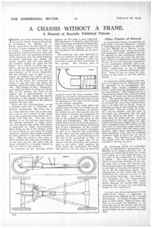
There are two cross-members, to use a familiar term for a somewhat unfamiliar construction. The front one is in a line with the front_end of the gearbox, and is, as a matter of fact, made up of two projecting arms which are integral with that box. The rear crossmember is at the extreme rear end of the tubular extension to which reference has already been made. The chassis is suspended on these cross-members, there being, in one of the designs which -we have before DA, two pairs of simple cantilever springs, these being attached, at their centres, to the said cross-members. They are fixed to the axles at their forward and rearward extremities, as the case may be, the other ends all being attached to a bracket located at the rear end of the gearbox.
A reference to the drawing which appears on this page is now suggested. i The illustration n question demonstrates that the springs are disposed diagonally, 'their ends being widest apart osis the axles and closest together where they are attached to the bracket on the gearbox.
The crossbars are also intended to serve as supports for the body, and, for the purpose, are prolonged a little beyond the points of their attachment to the springs. The steering gear: is mounted inside the front, crossbar. The pedals are carried by the gearbox casting; whilst the change-speed and brake levers are mounted in the centre of the chassis on the tubular extension.
Inaccessibility is tho fault which one Would expect to find on a chassis so designed, and it is, therefore, of particular interest to note that special care has been taken to obviate any complaints on that score. A large hand-hole in the top of the gearbox gives access to the clutch and transmission. The engine is bolted direct to the front of the gearbox, and may be removed without disturbing any of the components of the chassis. To facilitate this last-named operation, as well as to improve the accessibility of the clutch and the mechanism of the gearbox, the clutch shaft telescopes into the end of the crankshaft, so that, on the one hand, the engine may be removed without disturbing the gearbox, and, on the other, after pushing the shaft inside the crankshaft, the shafts and gears of the box may be removed.
Other Patents..,of Interest.
A complicated-looking arrangement of multi-Stage internal-combustion turbine is illustrated and described in specification No. 196,931, by L. Dufour, It embodies a multi-stage turbo-compressor and exhauster, which compiqsses the air for delivery to the combustion chamber and exhausts the gas from the last turbine. There is a regenerator which heats the air on its way from the compressor to the combustion chamber, and a refrigerator which cools the exhaust gas before redelivering it as a cooling medium, to the internal-combustion turbine. Some of 'the air from the compressor is also used to cool the turbine wheels.
An ingenious rotary engine is the subject of a patent by C. Chilowsky, and he describes it in specification No.
■ 193,408. This engine embodies two rotors, which may be designated external and internal. The internal one is a .comparatively thick disc, into the outer , periphery of which are cut a number of cups. The external rotor is in the form of a rectangular trough designed partly to surround the rim of the internal rotor and to be kept full of liquid, which is retained in place in the trough by centrifugal force. The two rotors are eccentric, one to another, and the cups in the inner one alternately dip into and leave the liquid in the outer. As they leave they are filled with air, which is compressed as the cups' again enter the ,liquid and dip more deeply into it. The fuel is supplied from the interior of the inner disc to secondary cups, which are in communication with the main, cups. Ignition takes place spontaneously in these sec.ondany cups, and the resulting explosion tends to drive the air ont of the cups. This tendency is resisted by the liquid, .and the resultant force is utilized in driving the discs.
An interesting design of carburetter silencer is described in specification No. 209,676, by D. Napier and Son, Ltd. It consists of a short elbow pipe, the outlet from which is of the same diameter as • the inlet to the carburetter to which it
is bolted. The inlet portion of this elbow is twice the diameter of the outlet, and into it there are inserted two short flanged tubes the diameter of which is half that of the pipe, the flanges serving to fill the intervening space. The arrangement of the tubes will be best understood by .reference to one of the accompanying drawings. Air enters by one, emerging into the comparatively' large space between the -two, passes thence through the second tube, again emerging into a large area and passing thence to the carburetter.
A simple non-skid attachment for twin rubber-tyred wheels is described in specification No. 209,679, by W. Coxhead and another. A number of these fittings goes to each wheel. Each of them consists of a central bar designed to lie along the top of the groove, and having short projecting arms arranged in staggered relation to one another along each side,