


A New Differential Mechanism
Page 52
If you've noticed an error in this article please click here to report it so we can fix it.
A CCORD1NG to patent No. 681,604, 1-1 the conventional differential always directs greater power to the wheel more unable to use it, that is, a slipping wheel. An attempt to improve matters in this respect is described in the patent, which comes from M. Casa-Massa, Hotel Wellington, New York, U.S.A.
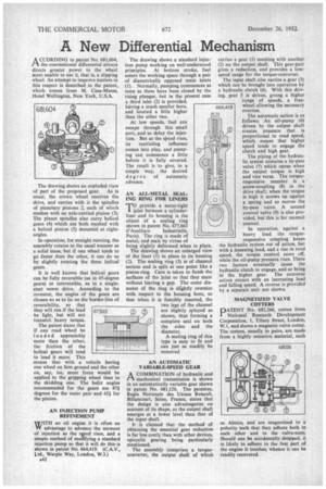
The drawing shows an exploded view of part of the proposed gear. As is usual, the crown wheel receives the drive, and carries with it the spindles of planetary pinions 2, each of which meshes with an axle-carried pinion (3). The planet spindles also carry helical gears (4) which are both meshed with a helical pinion (5) mounted at rightangles.
In operation, for straight running, the assembly rotates in the usual manner as a solid mass, but if one wheel tends to go faster than the other, it can do so by slightly rotating the three helical gears.
It is well known that helical gears can be fully reversible (as in 45-degree gears) or irreversible, as in a singlestart worm drive. According to the inventor, the angles of the gears are chosen so as to lie on the border-line of reversibility, so that they will run if the load be light, but will not transmit heavy torque.
The patent states that if one road wheel be 10 a ded appreciably more than the other, the friction of the helical gears will tend to load it more. This means that with a vehicle having one wheel on firm ground and the other on, say, ice, more force would be applied to the gripping wheel than to the skidding one. The helix angles recommended for the gears are 47-1degrees for the outer pair and 42:t for the pinion.
AN INJECTION PUMP REFINEMENT WITH an oil engine it is often an W advantage to advance the moment of injection as the speed rises, and a simple method of mollifying a standard injection pump so that it will do this-is shown in patent No. 664,419. (C.A.V., Ltd., Warple Way, London, W.3.) a42 The drawing shows a standard injection pump working on well-understood principles. At bottom stroke, fuel enters the working space through a pair of diametrically opposed main inlets (1). Normally, pumping commences as soon as these have been closed by the rising plunger, but in the present case a third inlet (2) is provided, having a much smaller bore, and located a little higher than the other two.
At low speeds, fuel can escape through this small port, and so delay the injection. But as the speed rises,
its restricting influence comes into play, and pumping can commence a little before it is fully covered. The result is to give, in a simple way, the desired deg r ee of automatic advance.
AN ALL-METAL SEALING RING FOR LINERS
T°provide a water-tight joint between a cylinderliner and its housing is the object of a sealing ring shown in patent No. 677,663
(l'Auxiliare Industrielle, Paris). The ring is made of metal, and seals by virtue of being slightly deformed when in place.
The drawing shows an enlarged view of the liner (1) in place in its housing (2). The sealing ring (3) is of channel section and is split at one point like a piston-ring. Care is taken to finish the surfaces of the joint so that they mate without leaving a gap. The outer diameter of the ring is slightly oversize With respect to the housing bore, so that when it is forcibly inserted, the two legs of the channel are slightly splayed as shown, thus forming a complete seal on both the sides and the diameter.
A sealing ring of this type is easy to fit and can Just as readily be removed.
AN AUTOMATIC VARIABLE-SPEED GEAR
ACOMBINATION of hydraulic and mechanical transmission is shown in an automatically variable gear shown in patent No. 681,126. The patentee, Regie Nationale des Usines Renault, Billancourt, Seine, France, states that the design is also advantageous on account of its shape, as the output shaft emerges at a lower level than that of the input shaft.
It is claimed that the method of obtaining the essential gear reduction is far less costly than with other devices, epicyclic gearing 'being particularly mentioned.
The assembly comprises a torqueconverter, the output shaft of which
carries a gear (I) meshing with another (2) on the output shaft. This gear-pair gives a reduction, and provides a lowspeed range for the torque-converter.
The input shaft also carries a gear (3) which can be brought into operation by a hydraulic clutch (4). With this driving, gear 5 is driven, giving a higher 'range of speeds, a freewheel allowing the necessary overrun.
The automatic action is as follows: An oil-pump (6) driven by the output shaft creates pressure that is proportional to road speed, which means that higher speed tends to engage the clutch and high gear.
The piping of the hydraulic system contains a by-pass valve (7) which opens when the output torque is high and vice versa. The torqueresponsive member is a screw-coupling (8) in the drive shaft; when the torque is high it screws up against a spring and so moves the by-pass valve. A second control valve (9) is also provided, but this is for manual control.
In operation, against a heavy load the torque responsive coupling keeps the hydraulic system out of action, but with a lessening load, and a rise in road speed, the torque control eases off, while the oil-pump pressure rises. These two factors eventually cause the hydraulic clutch to engage, and so bring in the higher gear. The converse action occurs with an increasing load and falling speed. A reverse is provided by a separate unit not shown.
MAGNETIZED VALVE COTTERS
PATENT No. 682,266, comes from National Research Development Corporation, 1, Tilney Street, London, W.1, and shows a magnetic valve cotter. The cotters, usually in pairs, are made from a highly retentive material, such
as Alnico, and are magnetized to a polarity such that they adhere both to each other and to the valve-stern. Should one be accidentally dropped, it is likely to adhere to the first part of the engine it touches, whence it can be readily recovered.