


A New Hydraulic Servo Hand Brake
Page 47
If you've noticed an error in this article please click here to report it so we can fix it.
ALOCKHEED hydraulic servo hand brake has been designed for use on passenger and heavy goods vehicles which are ,fitted with the hydraulic servo braking system and hydraulic accumulator. The hydraulic accumulator—or constant-flow pump, as it is often termed—delivers hydraulic pressure to the hand-brake servo, which has a boost ratio of 3 to I.
The maximum work which can be done by the ervo is 3,693 in.-lb. at 1,000 lb. per sq. in. pressure from the accumulator Should the accumulator pressure fail, there is still a direct mechanical effort applied to the ram push-rod. Furthermore, should the accumulator pressure decrease while the vehicle is parked, the applied effort will not be &creased, as the brakes will still be held " on " by the hand-brake ratchet.
The action is fully progressive, gives the driver ample control over the brakes and confidence in controlling the vehicle, without requiring undue effort on the hand-brake lever. Small and compact, the un;t weighs only 13 lb.
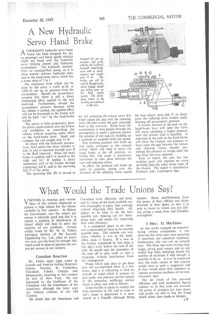
In Circuit with the hydraulic accumulator, fluid enters the servo cylinder at port A and is returned through port B to the fluid reservoir. When the hand brake is applied, rod C is moved to the right and lint D applies a direct mechanical pull to the brakes through connecting rod E, and to the operating link F cf the servo.
The operating link (F) is moved to the left, actuating the release valve (0) which closes the gap with the reducing valve (H) and covers the port returning fluid to the reservoir. Fluid from the accumulator is then passed through the passageways to apply a pressure against the annulus of the ram (I), building up a pressure as supplied from the pump.
This working pressure will build up and apply assistance to the manual action, which will tend to move the hand brake to the off position, or, failing this, will cause a reactionary movement to take place between the ram and reducing valves.
In effect, the pressure will build up until its reaction, acting over the diameter of the reducing valve, equals the load placed upon link F, at which point the reducing valve re-seats itself, shutting off accumulator pressure.
A further increase in the pull on the hand-brake lever will open the valve still more, admitting a higher pressure until this greater load is equalled. A reduction in the pull on the hand brake will allow the trapped ram pressure to force open the gap between the release and reducing valves, thereby permitting the pressure to escape until the new force has been opposed.
Easy to install, the unit has few working parts and requires no more servicing than the other brake units of the chassis. The maker is Automotive Products, Ltd., Leamington Spa.